This digital library houses the book on Oncology and Orthopedic Oncosurgery.

It includes academic lectures, presentations from national and international congresses, published papers, case discussions, performed surgical procedures, and proprietary techniques developed.

The digital format was chosen because the web allows the inclusion of texts with numerous visual resources, such as images and videos, which would not be possible in a printed book.

The content is intended for students, healthcare professionals, and the general public interested in the field.

Osteosarcoma of the Femur

Osteosarcoma of the femur - Non-conventional knee prosthesis - Length discrepancy - Epiphysiodesis of the femur and tibia.

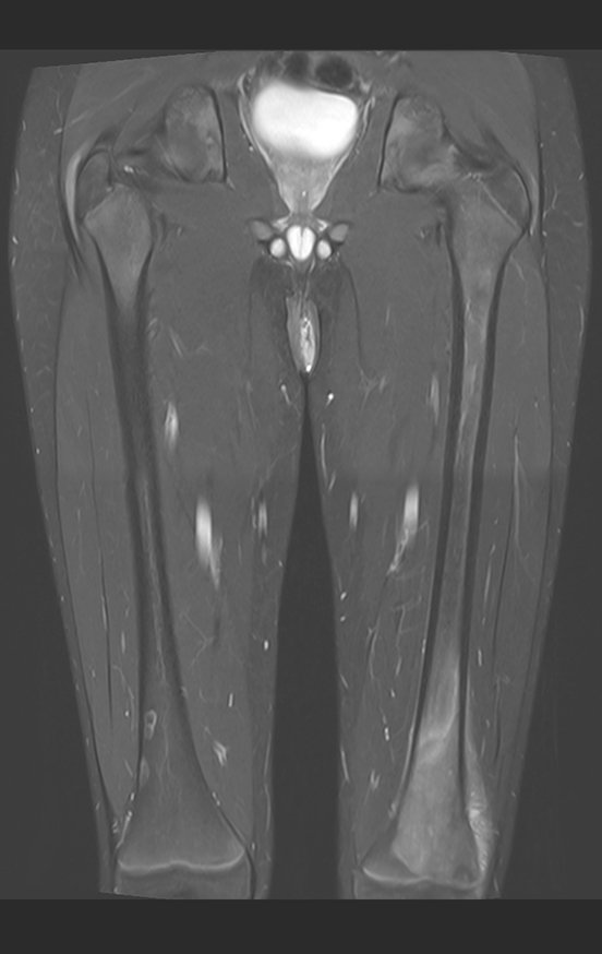
Osteosarcoma of the Femur. Patient aged twelve years and six months, with pain in the left knee for three weeks. She underwent MRI which revealed a lesion in the distal metaphysis of the femur.
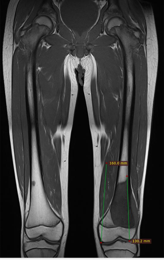
Figura 1: Lesão metafisária com baixo sinal em T1, comprometendo a cortical lateral e a placa de crescimento do fêmur esquerdo, seta em vermelho. Na metáfise femoral direita observamos duas lesôes na metáfise, próximo a cortical lateral.
Figure 1: Metaphyseal lesion with low signal intensity on T1, compromising the lateral cortex and the growth plate of the left femur, red arrow. In the right femoral metaphysis we observed two lesions in the metaphysis, close to the lateral cortex.
Figura 2: Extensa lesão metafisária, com reação perioteal lamelar fina e triângulo de Codmann. As lesões do lado direito são bem delimitadas, com características de lesão pseudo tumoral.
Figure 2: Extensive metaphyseal lesion, with thin lamellar perioteal reaction and Codmann's triangle. The lesions on the right side are well defined, with characteristics of a pseudo-tumorous lesion.
Figura 3: Rm axial T1 com tumor acometendo toda a região intramedular e as porções anterior, medial e posterior extracortical, desta região.
Figure 3: Axial T1 MRI with tumor affecting the entire intramedullary region and the anterior, medial and posterior extracortical portions of this region.
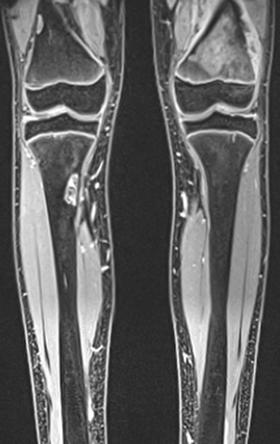
Figura 4: Rm centrada na lesão, evidenciando o comprometimento da metade lateral da placa de crescimento do fêmur esquerdo. Na metáfise distal do fêmur direito podemos observar duas lesões na face lateral e na metáfise proximal da tíbia deste mesmo lado vemos uma lesão na cortical medial.
Figure 4: MRI centered on the lesion, showing involvement of the lateral half of the growth plate of the left femur. In the distal metaphysis of the right femur we can see two lesions on the lateral surface and in the proximal metaphysis of the tibia on the same side we see a lesion in the medial cortex.
Figura 5: Rm axial com supressão de gordura, destaca a extensão extra cortical da lesão.
Figure 5: Axial MRI with fat suppression, highlighting the extra-cortical extension of the lesion.
Figura 6: Rm coronal T1, contraste. A seta em vermelho assinala a lesão heterogênea, agresssiva, com áreas de rarefação e áreas mais densas. No lado direito as setas amarelas destacam as lesões pseudo neoplásicas, já referidas.
Figure 6: Coronal MRI T1, contrast. The red arrow indicates the heterogeneous, aggressive lesion, with areas of rarefaction and denser areas. On the right side, the yellow arrows highlight the pseudo-neoplastic lesions, already mentioned.
Figura 7: Rm coronal pós contraste.
Figure 7: Post-contrast coronal MRI.
Figura 8: Rm axial, lesão sólida com grande captação de contraste. Figura 9: Rm axial destaca a lesão na tíbia contralateral, bem delimitada.
Figure 8: Axial MRI, solid lesion with high contrast uptake. Figure 9: Axial MRI highlights the well-defined lesion in the contralateral tibia.
Figura 10: Tomografia de 18/09/2015. Aseta vermelha aponta a densidade aumentada no canal medular e o tumor extracortical.
Figure 10: Tomography of 09/18/2015. The red arrow points to the increased density in the medullary canal and the extracortical tumor.
Figura 11: Tomografia em corte coronal, Seta vermelha assinalando a lesão na metáfise distal do fêmur. Seta amarela assinala a lesão pseudo neoplásica na cortical medial da tíbia direita.
Figure 11: Coronal tomography, Red arrow indicating the lesion in the distal metaphysis of the femur. Yellow arrow indicates the pseudoneoplastic lesion in the medial cortex of the right tibia.
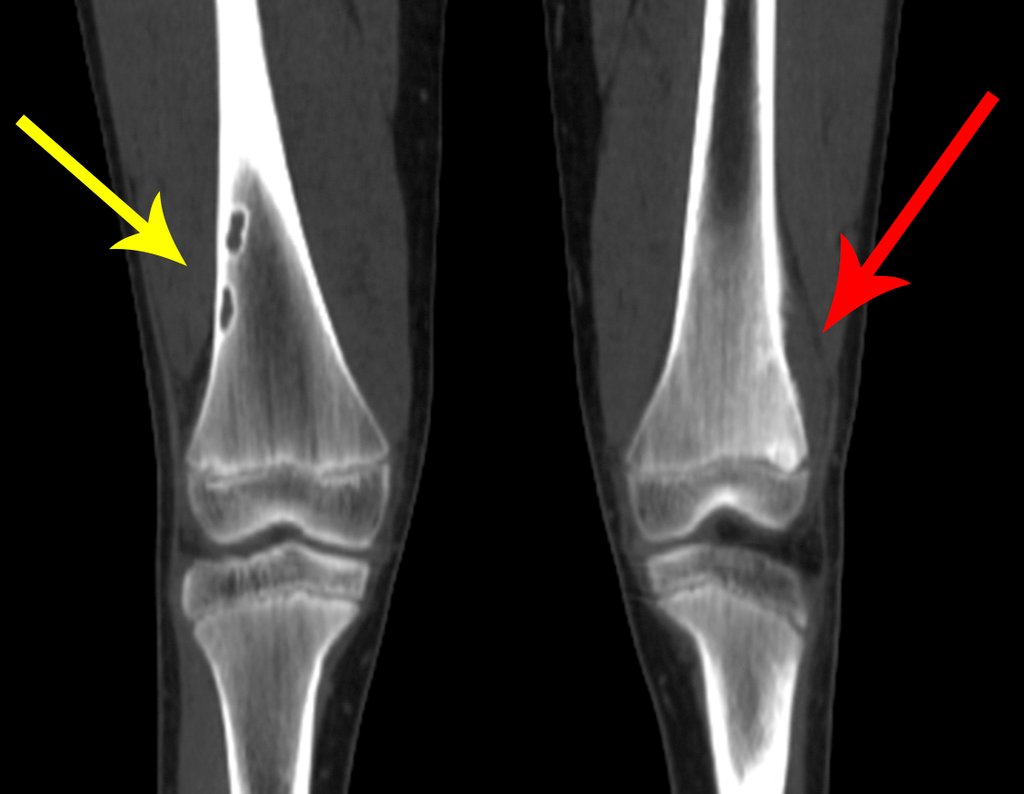
Figura 12: Tomografia coronal, duas lesões bem delimitadas , pseudo tumoral na cotical lateral do fêmur direito, seta amarela. Tumor na metáfise do fêmur esquerdo, seta vermelha.
Figure 12: Coronal tomography, two well-defined, pseudo-tumorous lesions on the lateral side of the right femur, yellow arrow. Tumor in the metaphysis of the left femur, red arrow.
Figura 13; Laudo da tomografia de tórax revelando nódulo calcifiado no segmento superior do lobo inferior esquerdo, cicatricial.
Figure 13; Chest tomography report revealing a calcified nodule in the upper segment of the left lower lobe, scarring.
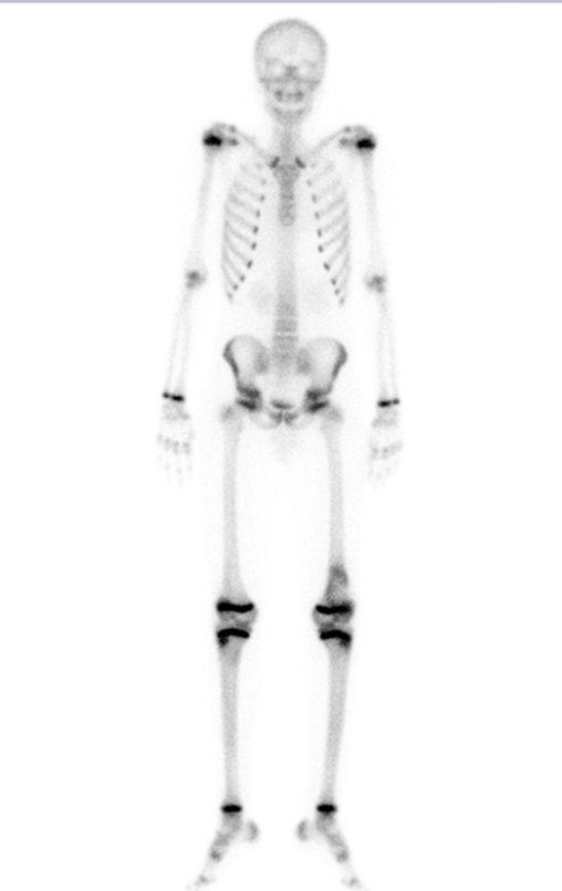
Figura 14: Cintilografia com captação alterada apenas na metáfise femoral esquerda. As lesões pseudo tumorais não captam. São cicatrizes, lesões latentes.
Figure 14: Scintigraphy with altered uptake only in the left femoral metaphysis. Pseudo-tumorous lesions do not capture. These are scars, latent injuries.
Figura 15: Cintilografia vista posterior, com captação alterada apenas na metáfise femoral esquerda. As lesões pseudo tumorais não captam. São cicatrizes, lesões latentes.
Figure 15: Scintigraphy seen posteriorly, with altered uptake only in the left femoral metaphysis. Pseudo-tumorous lesions do not capture. These are scars, latent injuries.
Figura 16: Cintilografia localizada do joelho esquerdo, com captação alterada.
Figure 16: Localized scintigraphy of the left knee, with altered uptake.
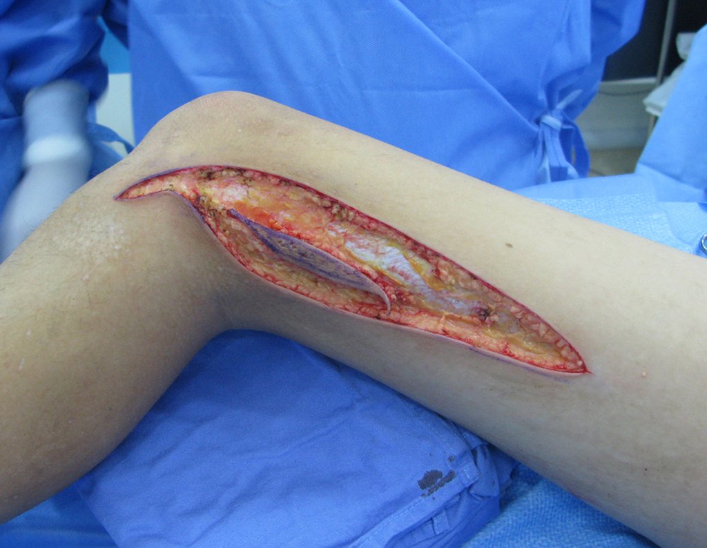
Figura 17: Pet-Cet localizado do joelho esquerdo com captação alterada.
Figure 17: Pet-Cet located on the left knee with altered uptake.
With this assessment, we decided to perform the biopsy from the lateral aspect of the femur, under tomography control.
Figura 18: Rm axial, biópsia planejada na face medial, no tumor extra-cortical.
Figure 18: Axial MRI, planned biopsy on the medial face, in the extra-cortical tumor.
Figura 19: Rm axial, com a delimitação do local onde queremos colher material. Na lesão extra-cortical, no septo da inserção posterior da fascia muscular.
Figure 19: Axial Rm, with the delimitation of the location where we want to collect material. In extra-cortical injury, in the septum of the posterior insertion of the muscular fascia.

It is not enough to simply say that we should perform the biopsy on the “side” of the surgical incision. It is necessary to carefully plan what we call the SURGICAL INCISION PATH.

We should not cross the vastus lateralis muscle but rather look for the direction of the posterior intercept of the fascia that covers the vastus laterally.

This way we will have a resection that will preserve the entire muscle, aiming for an anatomical resection of the biopsy site. In addition, we will be helping to restore better functionality.

Pay close attention to the patient’s positioning to best execute what was planned.

Figura 20: Posicionamento do paciente em decúbito prono, para fascilitar a acesso póstero lateral da biópsia, seta vermelho. A seta amarela assinala o controle tomográfico do ponto exato para a biópsia.
Figure 20: Positioning the patient in the prone position, to facilitate the posterolateral biopsy access, red arrow. The yellow arrow indicates the tomographic control of the exact point for the biopsy.
Figura 21: Com o paciente já sedado, confere-se o ponto escolhido e realiza-se infiltração de anestesico no local.
Figure 21: With the patient already sedated, the chosen point is checked and anesthetic is infiltrated into the area.
Figura 22: Documentação do disparo da agulha de Tru-cut, no ponto exato escolhido.
Figure 22: Documentation of the Tru-cut needle firing, at the exact chosen point.
Figura 23: A patologista na sala analisa o material obtido. Verifica a quantidade obtida, as coletas necessárias para imunoistoquímica, citometria de fluxo, cultura, se é representativo da lesão, etc.
Figure 23: The pathologist in the room analyzes the material obtained. It checks the quantity obtained, the collections required for immunohistochemistry, flow cytometry, culture, whether it is representative of the lesion, etc.
Pathological anatomical examination confirms the diagnostic hypothesis, classifying the lesion as chondroblastic osteosarcoma. The patient undergoes cycles of neo-adjuvant chemotherapy and we begin planning the surgery, taking x-rays with a ruler and MRI after induction chemotherapy.
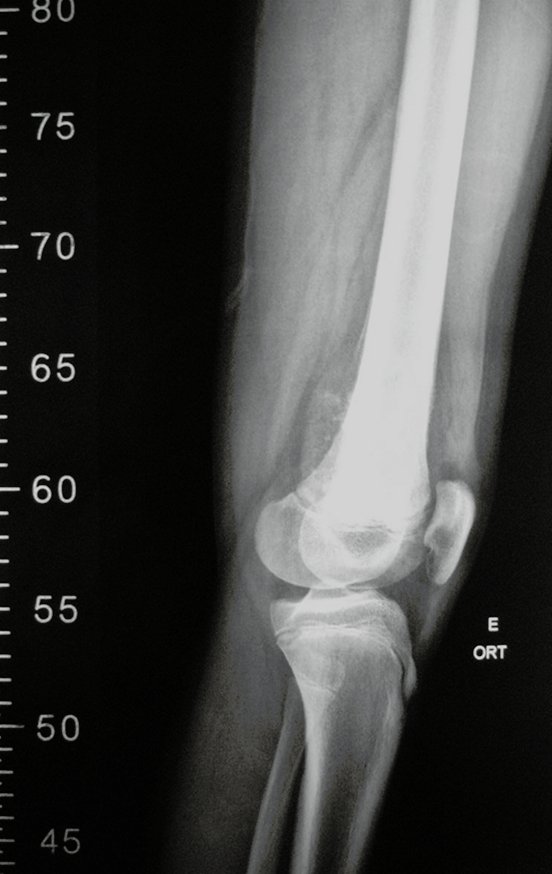
Figura 24: Radiografia do 1/3 distal do fêmur, incluindo o 1/3 proximal da tíbia, frente.
Figure 24: Radiograph of the distal 1/3 of the femur, including the proximal 1/3 of the tibia, front.
Figura 25: Radiografia do 1/3 distal do fêmur, incluindo o 1/3 proximal da tíbia, perfil.
Figure 25: Radiograph of the distal 1/3 of the femur, including the proximal 1/3 of the tibia, profile.
Figura 26: Rm coronal T1 pós quimioterapia, avaliando a extensão da lesão.
Figure 26: Coronal T1 MRI after chemotherapy, assessing the extent of the lesion.
Figura 27: Rm sagital T1, com supressão de gordura, pós quimioterapia, avaliando a extensão da lesão. Observamos que o paciente apresenta acentuação do antecurvatum do fêmur.
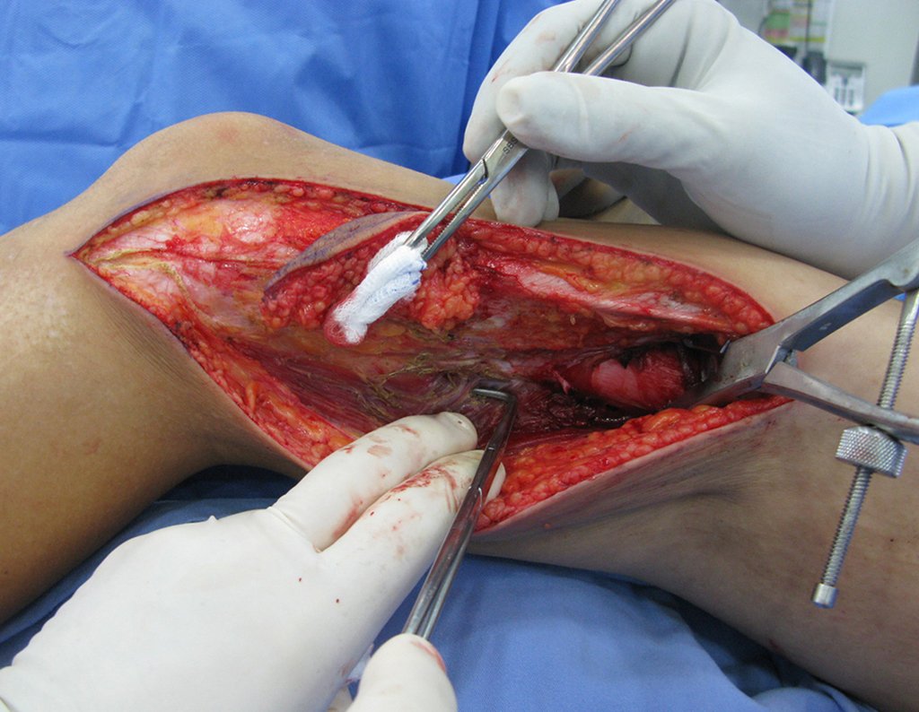
Figure 27: Sagittal T1 MRI, with fat suppression, post chemotherapy, assessing the extent of the lesion. We observed that the patient presents accentuation of the antecurvatum of the femur.
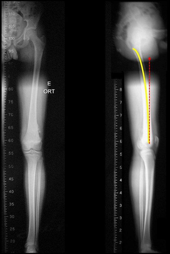
This patient has an antecurvatum of the femur that requires careful planning so that the femoral stem does not pierce the anterior cortex, creating a false path.
Figura 28: Eescanometria em perfil destacando o antecurvatum. Projeção do trajeto falso que a haste reta da prótese ocasiona.
Figure 28: Scanometry in profile highlighting the antecurvatum. Projection of the false path caused by the straight stem of the prosthesis.
Figura 29: Modelo disponível em outubro de 2015, à esquerda. Conecção redonda dos segmentos, setas de cor rocha, parafusos pequenos de fixação, setas em vermelho. À direita, novos módulos solicitados. Bloqueios retangulares nas conecções, setas amarelas A e B; parafusos de fixação, mais fortes, setas em branco. Conexão, retangular no encaixe do corpo da nova prótese, seta azul .
Figure 29: Model available in October 2015, on the left. Round connection of segments, rock-colored arrows, small fixing screws, red arrows. On the right, new requested modules. Rectangular blocks in connections, yellow arrows A and B; fixing screws, stronger, blank arrows. Connection, rectangular in the fitting of the new prosthesis body, blue arrow.
Figura 30: Solicitação à ANVISA para autorização de confecção de modêlo especial de prótese.
Figure 30: Request to ANVISA for authorization to manufacture a special prosthesis model.
Figura 31: Prótese confeccionada sob encomenda, com os encaixes retangulares entre os módulos, bloqueando a rotação, setas amarelas A e B. As setas azuis assinalam o encaixe retangular do corpo da prótese. As setas brancas destacam os parafusos de fixação, mais fortes e em maior número. A seta laranja aponta a haste calibrada para o canal medular do paciente.
Figure 31: Custom-made prosthesis, with rectangular fittings between the modules, blocking rotation, yellow arrows A and B. The blue arrows indicate the rectangular fitting of the prosthesis body. The white arrows highlight the stronger and more numerous fixing screws. The orange arrow points the calibrated rod to the patient's spinal canal.

Scanometry in profile highlights the antecurvatum, marked in yellow, and the false path that the straight stem of the prosthesis would take, making it necessary to plan the special length of the stem and its thickness.

The model available in October 2015 had a round connection between the modules. Over time, they may loosen and rotate between them. The new modules requested feature rectangular blocks in the connections, yellow arrows A and B , in figure 29, in addition to the fixing screws being now stronger, white arrow. The new body of the prosthesis also features the rectangular fitting lock.

We requested ANVISA for authorization to manufacture a special model of this prosthesis, with the consent of the patient’s legal guardian, a minor, attesting to being aware that this model “Does not have the safety and efficacy evaluated by Anvisa”!!!

The prosthesis was made to order, with rectangular fittings between the modules and also in the fitting with the body of the prosthesis, blocking rotation. The rod was designed with the appropriate caliber for the patient’s spinal canal.

Figura 32: Rm sagital, pós contraste, pós quimioterapia neoadjuvante, revelando a extensão do tumor , que compromete a placa de crescimento e a epífise femoral;
Figure 32: Sagittal MRI, post contrast, post neoadjuvant chemotherapy, revealing the extent of the tumor, which compromises the growth plate and the femoral epiphysis;
Figura 34: Rm axial pós contraste, pré operatória. Grande tumor extracortical.
Figure 33: Axial T1 MRI, favorable response to chemotherapy, with decreased edema and ossification of the lesion. Figure 34: Post-contrast axial MRI, pre-operative. Large extracortical tumor.
Figura 35: Paciente internado para cirurgia, demarcação pré-operatória.
Figure 35: Patient admitted for surgery, preoperative demarcation.
O paciente recebe o pré anestésico no apartamento, onde também se realiza a demarcação para identificação do lado a ser operado.
Figura 36: Preparo do paciente para a cirurgia. Assepsia e antissepsia.
Figure 36: Preparing the patient for surgery. Asepsis and antisepsis.
Figura 37: Demarcação da incisão, com exerese do trajeto da biópsia.
Figure 37: Demarcation of the incision, with excision of the biopsy path.
After asepsis and antisepsis, we demarcated the surgical incision with excision of the biopsy path. We operate without garroting the limb, cautiously performing hemostasis, step by step.
 
Figura 38: Cirurgia sem garroteamento do membro. Hemostasia cautelosa do sub-cutâneo.
Figure 38: Surgery without tourniquet of the limb. Cautious subcutaneous hemostasis.
Figura 39: Incisão por planos anatômicos, contorando o trajeto da biópsia posteriormente.
Figure 39: Incision along anatomical planes, contouring the biopsy path afterwards.

Note that the surgical field is dry, without bleeding. We detach the periosteum above the lesion limit and place a locked forceps to aid exposure.

Most of the dissection is carried out with an electric scalpel, from the subcutaneous layer, with low voltage, 20 cutting and 20 coagulation, in spray mode, calibrated to operate slowly, cauterizing slowly and avoiding burn injury.

Figura 40: Descolamento da cápsula articular antero lateral, juntamente com o vasto lateral intacto. A seta amarela destaca o trajeto da biópsia sendo ressecado juntamente com a peça cirúrgia.
Figure 40: Detachment of the anterolateral joint capsule, together with the vastus lateralis intact. The yellow arrow highlights the biopsy path being resected along with the surgical specimen.
Figura 41: Liberação do canal de Hunter, rebatendo os vasos femorais posteriormente.
Figure 41: Release of the Hunter's canal, reflecting the femoral vessels posteriorly.
Touch is essential to “see” the limits of the tumor and to be able to preserve as much healthy tissue as possible, without the risk of penetrating the lesion, providing the best possible function.
Video 1: Cautious dissection, without garroting the limb, with electrocautery in “spray” mode and at low voltage.

We continue releasing the lesion, “”seeing” it with our fingers.

Figura 42: Dissecção contornando posteriormente a lesão, "enchergando" com os dedos. A seta amarela destaca a pele e o trajeto da biópsia rebatidos, sendo ressecados juntamente com o tumor.
Figure 42: Dissection contouring the lesion posteriorly, "filling" it with the fingers. The yellow arrow highlights the skin and the biopsy path that were reflected, being resected together with the tumor.
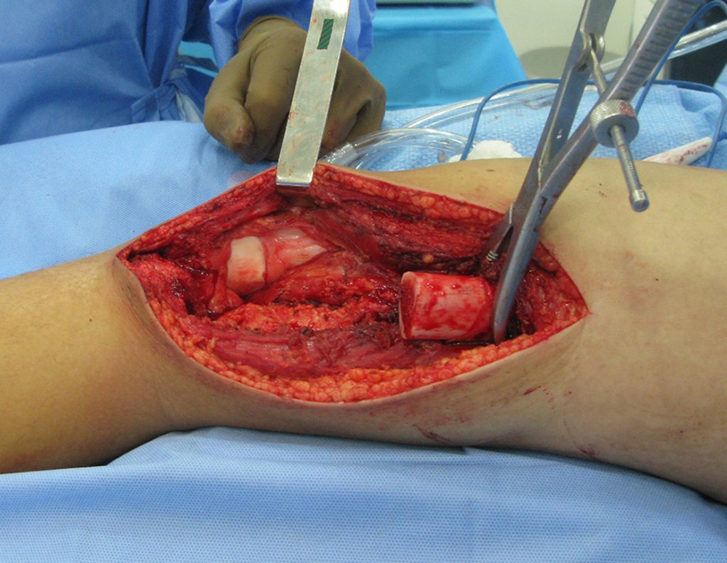
Figura 43: Abertura da cápsula articular. Trajeto da biópsia ressecado conjuntamente com o tumor.
Figure 43: Opening of the joint capsule. Biopsy tract resected together with the tumor.
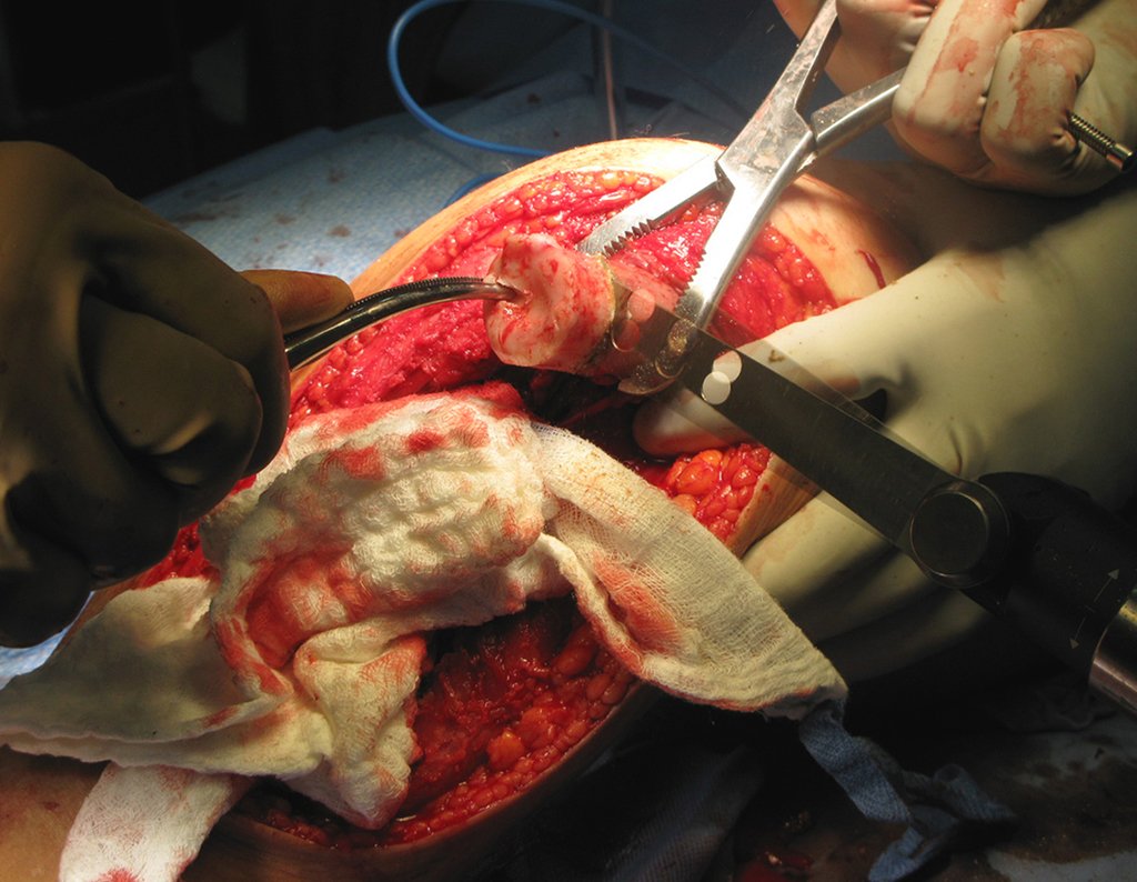
After contouring the entire tumor, we demarcate the cut and perform the osteotomy with an electric saw or a Gigle saw, video 2.

Video 2: Osteotomy with Gigle saw.

Figura 44: Osteotomia com serra de Gigle.
Figure 44: Osteotomy with Gigle saw.
Figura 45: Após a osteotomia prosseguimos liberando a cápsula posterior, completando a ressecção do tumor,
Figure 45: After the osteotomy, we continued releasing the posterior capsule, completing the resection of the tumor,

Video 3: Release of the cruciate ligaments.

With the tumor removed, we checked the measurement of the segmental defect, assembled the prosthesis and checked the length, comparing it with the size of the resected piece.
 
Figura 46: Leito operatório, tumor ressecado
Figure 46: Operating bed, resected tumor
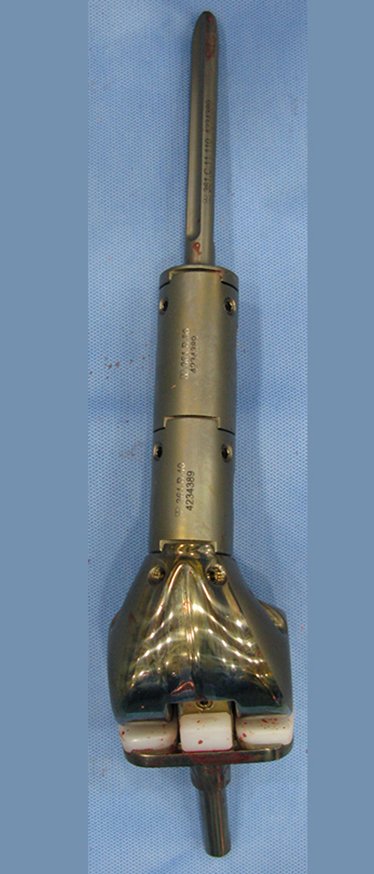
Figura 47: Componentes da prótese de titâneo e articulação de polietileno.
Figure 47: Components of the titanium prosthesis and polyethylene joint.
Figura 51: Orientação do componente tibial alinhando-o com a perna.
Figure 48: Assembled endoprosthesis, frontal view.
Figura 49: Endoprótese montada, visualização de perfil.
Figure 49: Assembled endoprosthesis, profile view.

We then prepare the tibial plateau to insert the tibial component of the prosthesis.

We only remove the cartilage from the tibia, removing the minimum amount of spongy bone tissue, which is firmer just below the cartilage. We regularize the tibial plateau, so that the surface is parallel to the ground, correcting the cut thickness, since the medial plateau is inferior to the lateral one.

This plateau osteotomy can be performed with a power saw or carefully with wide, sharp osteotomes.

Video 4: Regularization of the tibial plateau with osteotomes.

We identified the medullary canal of the tibia and milled it manually. The orientation of the thiial component is marked by aligning it with the leg. We check the rotation before going deeper and testing the tibial prosthesis.
Figura 50: Identificação do canal medular da tíbia e fresamento manual.
Figure 50: Identification of the tibial medullary canal and manual milling.
Figura 51: Orientação do componente tibial alinhando-o com a perna.
Figure 51: Orientation of the tibial component, aligning it with the leg.
Figura 52: Conferencia da orientação de rotação neutra, antes do aprofundamento do sulco para acomodar a prótese.
Figure 52: Checking the neutral rotation orientation, before deepening the groove to accommodate the prosthesis.
Figura 53: Posicionamento do componente tibial da prótese e teste antes da cimentação.
Figure 53: Positioning the tibial component of the prosthesis and testing before cementing.
We checked the length of the prosthesis, adjusted the size of the resection and widened the femoral canal.

Video 5: After accommodation of the tibial component, the resection is checked and equalized with the size of the femoral prosthesis.

Figura 54: Regularização do tamanho da ressecção.
Figure 54: Regularization of resection size.
Figura 55: Alargamento do canal medular do fêmur
Figure 55: Enlargement of the medullary canal of the femur
We started widening the canal with a manual milling cutter.

Video 6: Widening of the medullary canal, initially with a manual drill.

Then we complement it with motor milling.

Video 7: Complementing the widening with a motorized milling cutter.

We check the width and length of the femoral stem.

Video 8: Channel widening depth test.

We regularize the cut, leaving a plane perpendicular to the diaphysis.

Video 9: Regularization of the top of the osteotomy.

We regularize the cut, leaving a plane perpendicular to the diaphysis.

Video 10: Compaction of the first prosthesis module.

Video 11: Compaction of the second prosthesis module and femoral stem.

Video 12: Fixing with four screws in each connection.

Once the components have been assembled and tested, we carry out the cementation, starting with the tibial component, reduce it and carry out the last text, before placing the femoral plug and final cementation.

 
Figura 56: Cimentação do componente tibial.
Figure 56: Cementation of the tibial component.
Figura 57: Mensuração da profundidade do canal para colocação do plug de contenção do cimento.
Figure 57: Measuring the depth of the channel for placing the cement containment plug.

Video 13: Cementation of the tibial component and removal of excess cement.

Video 14: Cementation of the femoral component.

With this model of blocked connections there is no possibility of correction after cementation, and the team must pay all attention at this time to precise positioning. The introduction of the prosthesis into the femoral canal must be oriented in neutral rotation, aligning the sides: side of the prosthesis with the side of the femur.
Figura 58: Posicionamento da prótese femoral e retirada do excesso de cimento.
Figure 58: Positioning the femoral prosthesis and removing excess cement.
Figura 59: Redução dos componentes e flexão máxima, com alinhamento correto do pé, perna e coxa.
Figure 59: Reduction of components and maximum flexion, with correct alignment of the foot, leg and thigh.
After cementing the femur, we must reduce the tibial and femoral components and flex the knee, paying close attention to the alignment of the foot, leg and thigh, as while the cement is polymerizing we can make adjustments to accommodate small degrees of rotation.

Video 15: Testing the functional range of the knee with the prosthesis.

Hemostasis is reviewed, we add soft tissue hemostatic, aiming to reduce bleeding and we place the drain.
Figura 60: Revisão da hemostasia.
Figure 60: Hemostasis review.
Figura 61: Colocação de hemostático de tecidos moles.
Figure 61: Placement of soft tissue hemostat.

Video 16: Placement of soft tissue hemostat.

Figura 62: Peça ressecada, com o trajeto da biópsia e o segmento de ajuste, retirado do fêmur, visualização dorsal.
Figure 62: Resected piece, with the biopsy path and the adjustment segment, removed from the femur, dorsal view.
Figura 63: Peça ressecada, com o trajeto da biópsia e o segmento de ajuste, retirado do fêmur. visualização ventral.
Figure 63: Resected piece, with the biopsy path and the adjustment segment, removed from the femur. ventral view.
Figura 64: Reinserção dos músculos gemeo medial e lateral, vasto lateral e fechamento por planos da ferida operatória.
Figure 64: Reinsertion of the medial and lateral twin muscles, vastus lateralis and closure of the surgical wound in layers.
Figura 65: Sutura da pele, colocação do dreno e curativo.
Figure 65: Suturing the skin, placing the drain and dressing.
On the first day after surgery, we checked the surgical wound and the drain output. If there was no significant output and we observed plasma in the drainage tube, we removed the drain 24 hours after surgery, starting walking training with a walker.
Figura 66: retirada do dreno no primeiro dia pós operatório
Figure 66: removal of the drain on the first day after surgery
Figura 67: Paciente em pé com carga, post-op 01.
Figure 67: Patient standing with weight, post-op 01.
Figura 68: Orientação para transferência do peso para o membro operado, "empurrando o chão".
Figure 68: Orientation for transferring weight to the operated limb, "pushing the floor".
Figura 69: retirada do dreno no primeiro dia pós operatório.
Figure 69: removal of the drain on the first day after surgery.
Figura 70: Paciente em pé com carga, post-op 01.
Figure 70: Patient standing with weight, post-op 01.
Figura 71: Orientação para transferência do peso para o membro operado, "empurrando o chão".
Figure 71: Orientation for transferring weight to the operated limb, "pushing the floor".
After removing the stitches, between the tenth and 15th day, physical therapy begins daily, under guidance.

Video 17: Walking with the immobilizer, on 01/05/2016, twenty days after surgery. (third week), walking slowly.

Video 18: Walking with the immobilizer, third week, guiding posture.

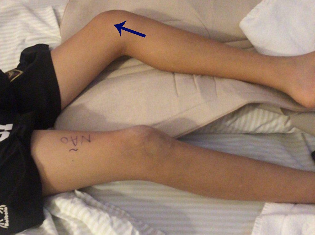
Note the slight flexion of the knee, due to the intentional lengthening of approximately 1.0 cm of the prosthesis, aiming to minimize the discrepancy in length that will occur with growth.

Video 19: Macha with the help of the physiotherapist’s two hands, faster, automating.

Video 20: Walking with the immobilizer and assistance, slight knee flexion.

Video 21: Starting to walk with a crutch, on 01/05/2016, three weeks after surgery.

All this evolution occurred on the same day, with the guidance of the physiotherapist, in the third week, after surgery. The next day the work continues, achieving the desired progress.

Video 22: Walking training, now with a long knee brace, removing the foot from the ground and slightly flexing the knee, on 01/06/2016, second day of assisted physiotherapy.

After two months, he walked with his knee free, still with a knee flexion attitude and slight limping.

Video 23: Walking with the knee free, on 02/17/2016, two months after surgery. Slight flexion and lameness.

Figura 72: Radiografia de 30/03/2016, post op 3 meses, frente.
Figure 72: Radiograph from 03/30/2016, post op 3 months, front.
Figura 73: Radiografia de 30/03/2016, post op 3 meses, perfil.
Figure 73: Radiograph from 03/30/2016, post op 3 months, profile.
Figura 74: Paciente em 30/03/2016, post op 3 meses, ainda com discreta atitude de flexão do joelho operado.
Figure 74: Patient on 03/30/2016, 3 months post op, still with a slight flexion of the operated knee.
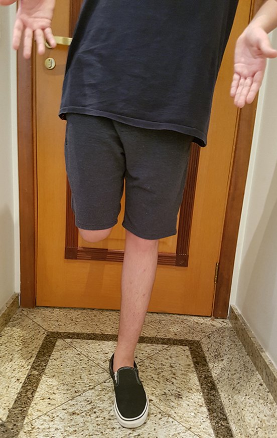
Figura 75: Paciente com carga total, monopodal.
Figure 75: Patient with full load, single leg.
Figura 75: Paciente com carga total, monopodal.
Figure 75: Patient with full load, single leg.

Video 24: March on 03/30/2016, after 3 months. Improvement of lameness.

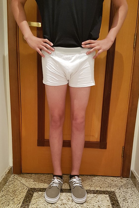
Figura 77: Paciente em 12/07/2016, post op 8 meses, extensão total dos joelhos, perfeito alinhamento dos MMII.
Figure 77: Patient on 07/12/2016, post op 8 months, full extension of the knees, perfect alignment of the lower limbs.
Figura 78: Carga total, monopodal, após oito meses.
Figure 78: Full load, single leg, after eight months.
Figura 79: Flexão simétrica, com carga total, oito meses pós op e dois meses depois do término da quimioterapia .
Figure 79: Symmetrical flexion, with full load, eight months post op and two months after the end of chemotherapy.
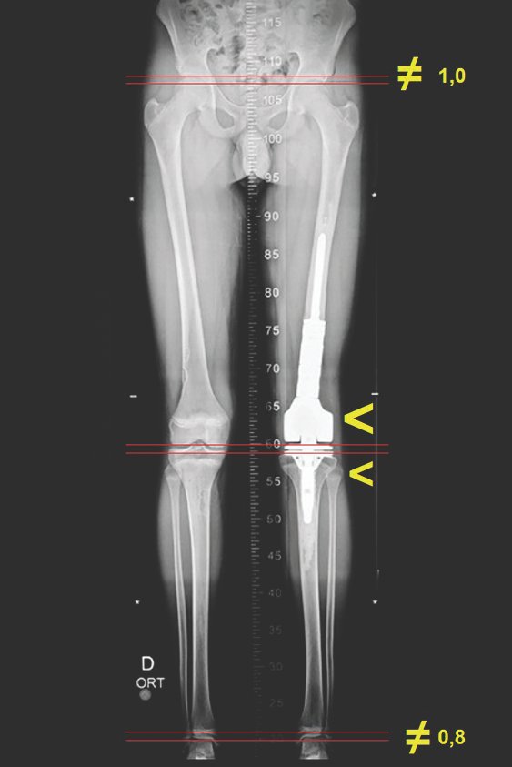
Figura 80: Escanometria revelando discrepância de 0,8 cm, às custas da tíbia e 1,0 cm às custas do fêmur, totalizando 1,8 cm de encurtamento.
Figure 80: Scanometry revealing a discrepancy of 0.8 cm, at the expense of the tibia and 1.0 cm at the expense of the femur, totaling 1.8 cm of shortening.

Video 24: Patient sailing, balancing with his lower limbs, in July 2016, after eight months of surgery.

Video 25: Skiing, in July 2016, after eight months of surgery.

Video 26: March on 07/12/2016, after 8 months. Symmetrical function, without lameness.

Although we left the operated limb longer, the patient had a significant growth spurt causing the length discrepancy. This stretch, however, corrected the flexion attitude of the operated knee. This metallic prosthesis causes a greater discrepancy in the length of the limbs because, in addition to the resection of the femoral plate, the tibial component greatly damages the growth plate, and blocks the remaining physis due to its cementation. With the patient off chemotherapy, we scheduled definitive epiphysiodesis of the growth plates of the femur and contralateral tibia, aiming to stabilize the discrepancy.

Figura 81: Cintilografia evidenciando fises férteis à direita, setas azuis, ausencia na projeção da prótese femoral e fechada na projeção da tíbia do lado esquerdo, setas vermelhas.
Figure 81: Scintigraphy showing fertile physes on the right, blue arrows, absence in the projection of the femoral prosthesis and closed in the projection of the tibia on the left side, red arrows.
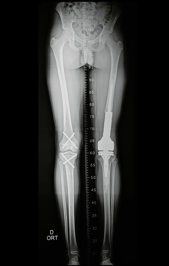
Figura 82: Escanograma com encurtamento, epifisiodese com parafusos canulados de rosca total, dois no fêmur e dois na tibia contralateral, visualização de frente e de perfil.
Figure 82: Scanogram with shortening, epiphysiodesis with full-thread cannulated screws, two in the femur and two in the contralateral tibia, frontal and profile view.

Realizada a epifisiodese do lado contralateral. Após três meses, podemos observar que o fechamento das fises já acontece, comparando as cintilografias pré, figura 81, e pós, figura 82.

Figura 83: Paciente em 14/12/2016, post op 1 ano, da cirurgia e depois de 3 meses da epifisiodese, extensão total dos joelhos, perfeito alinhamento dos MMII
Figure 83: Patient on 12/14/2016, post op 1 year, after surgery and after 3 months of epiphysiodesis, full extension of the knees, perfect alignment of the lower limbs
Figura 84: Carga total, monopodal, após 12 meses.
Figure 84: Full load, single leg, after 12 months.
Figura 85: Flexão simétrica, com carga total, um ano após a cirurgia.
Figure 85: Symmetrical flexion, with full load, one year after surgery.
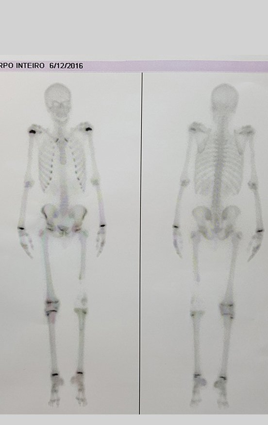
Figura 86: Cintilografia revelando apagamento da captação das placas de crescimento do fêmur e da tíbia contralateral, devido à epifisiodese
Figure 86: Scintigraphy revealing erasure of capture of the growth plates of the femur and contralateral tibia, due to epiphysiodesis
Figura 87: Escanograma de 10 de março de 2017, após seis meses da epifisiodese do fêmur e tíbia contralateral.
Figure 87: Scanogram of March 10, 2017, after six months of epiphysiodesis of the contralateral femur and tibia.
Figura 88: Lauda do escanograma, discrepância de 1,3 cm.
Figure 88: Scanogram report, discrepancy of 1.3 cm.
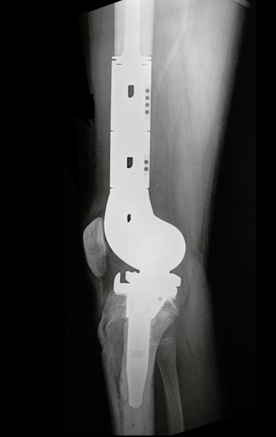
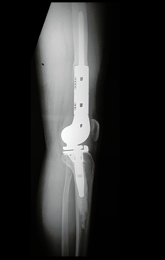
Figura 89: Radiografia pós operatória, após um ano e três meses, da ressecção e reconstrução com endoprótese.
Figure 89: Post-operative radiograph, after one year and three months, of resection and reconstruction with endoprosthesis.
Figura 90: Radiografia perfil, em 10/03/2017.
Figure 90: Profile x-ray, on 03/10/2017.
Figura 91: Função em março de 2017, após um ano e três meses.
Figure 91: Function in March 2017, after one year and three months.
Figura 92: Carga total monopodal no membro operado.
Figure 92: Single-leg total load on the operated limb.
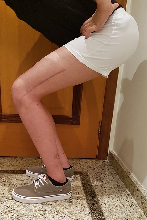
Figura 93: Flexão com carga simétrica, após 15 meses da cirurgia.
Figure 93: Flexion with symmetrical load, 15 months after surgery.
Figura 94: Aspecto cosmético da cicatrização após 15 meses.
Figure 94: Cosmetic appearance of healing after 15 months.

Video 27: Symmetric function in March 2017.

Video 28: Symmetric ability and function.

Author: Prof. Dr. Pedro Péricles Ribeiro Baptista

 Orthopedic Oncosurgery at the Dr. Arnaldo Vieira de Carvalho Cancer Institute

Hello! How can we assist you?