• Rua General Jardim, 846 cj 41 Higienópolis, São Paulo - SP

Author Archives: drpprb@gmail.com

This digital library houses the book on Oncology and Orthopedic Oncosurgery.

It includes academic lectures, presentations from national and international congresses, published papers, case discussions, performed surgical procedures, and proprietary techniques developed.

The digital format was chosen because the web allows the inclusion of texts with numerous visual resources, such as images and videos, which would not be possible in a printed book.

The content is intended for students, healthcare professionals, and the general public interested in the field.

drpprb@gmail.com

2edfb49eafd8d8946543d4504bf90c38 3

Eosinophilic Granuloma

[auto_translate_button]
Eosinophilic Granuloma – Pseudotumor Lesion. History: In 1938, Schairer diagnosed a child’s skull lesion as eosionphilic myeloma or eosinophilic osteomyelitis1. This condition was later described as a new clinical entity by Otani and Ehrlich in 1940 under the name Solitary Granuloma of Bone2.

Eosinophilic granuloma – Pseudo-tumorous lesion

Farber and Green, in 1942, demonstrated that the lesion could occur in a localized or multiple manner in the skeleton and possibly be related to Hand-Schuller-Christian disease and Letter-Siwe disease3.

In 1944, Jaffe and Lichtenstein introduced the term eosinophilic granuloma of bone4. The relationship of this lesion with the systemic forms of the disease was confirmed by Lichtenstein in his 1953 publication, encompassing them under the name Histiocytosis X5.

Currently, this entity is called Langerhans Cell Histiocytosis, which has four distinct clinical forms: Eosinophilic Granuloma, a form restricted to the skeleton, which can be localized or multiple; Hand-Schuller-Christian, chronic and disseminated form; Letter-Siwe, acute or subacute disseminated form and Hashimoto-Pritzker, postnatal form with spontaneous resolution6.

Introduction:  Solitary eosinophilic granuloma of the bone is the most common of the four forms of presentation of Langerhans Cell Histiocytosis, representing between 60% and 80% of cases7.

Among benign bone lesions, it is a rare entity, accounting for less than 1%8. It preferentially affects children and adolescents with a male predominance 2:19. Around 80% of patients are under 21 years of age and the majority of these are between five and 15 years of age6,7,9.

Some patients may begin with an isolated bone lesion and later develop multiple bone lesions. These cases can eventually evolve into systemic forms of the disease. When this occurs, it generally happens within the first six months of diagnosis and practically never after a year of evolution, which is a criterion for good prognosis, when no new lesions appear after this period of clinical follow-up10.

Hand-Schuller-Christian Syndrome is   the chronic form of Langerhans cell histiocytosis, characterized by systemic involvement with multiple bone lesions, mainly in the skull, exophthalmos and diabetes insipidus, affecting children over 3 years of age10.

Letter-Siwe Syndrome affects   children under three years of age, it is the acute or subacute form, also with systemic involvement. It presents with fever, otitis media, recurrent bacterial infections, anemia, hemorrhages, viceromegaly, diffuse and painful adenopathy with skin involvement similar to seborrheic eczema and generalized ostelitic lesions, with frequent progression to death10.

Hashimoto-Pritzker Syndrome is   a form of Langerhans cell histiocytosis that affects the skin exclusively. It affects children in the first month of life, manifesting with eczematous eruptions that resolve spontaneously6.

Etiology:  Unknown.

Genetics:  No significant reports regarding this.

Definition:  Eosinophilic Granuloma is a pseudotumor lesion, of unknown etiology, characterized by bone rarefaction that can be solitary or multiple. Microscopically, it presents a profile of mononuclear histiocytic cells, presenting antigens of dendritic origin, known as Langerhans cells, amidst the variable quantity of leukocytes, eosinophils, lymphocytes and giant cells.

Epidemiology:  Eosinophilic Granuloma mainly affects the axial skeleton, in this order: skull, pelvis, vertebrae, ribs, mandible, clavicle and scapula.

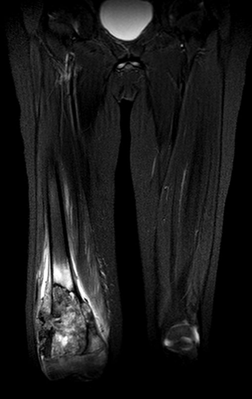
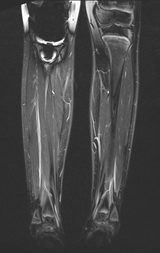
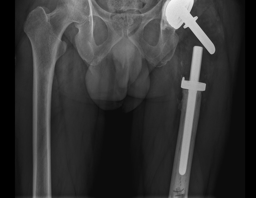
In the appendicular skeleton the femur, proximal region and diaphysis, humerus and tibia9. Most of the time it affects the diaphysis or metadiaphyseal region, being rare in the epiphysis7.

The spine represents 10% of cases in the pediatric population, the majority in the lumbar region.

In adults, it occurs more frequently in the ribs and less frequently in the spine, respectively 25% and 3%6.

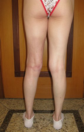
Clinical picture:  The most frequent symptom of Eosinophilic Granuloma is localized, throbbing, short-lasting pain, worsening at night associated with local heat and edema. When it affects the skull, this pain can be confused with other causes of headache.

Compromise of vertebral bodies can produce painful scoliosis. Any angular deviations are small, less than 100, as the vertebral flattening is usually uniform and rarely produces neurological symptoms. 

In other forms of Langerhans Cell Histiocytosis, systemic symptoms may be present such as fever, skin rush and diabetes insipidus. Hepatosplenomegaly can occur in Letter-Siwe syndrome, which is the most severe form of the disease6

Classification:  Eosinophilic granuloma can   manifest itself in two clinical forms:  Solitary  or  Multiple .

Laboratory tests:  Laboratory changes that can be found are an increase in ESR and CRP, and mild eosinophilia may occasionally occur in the blood count.

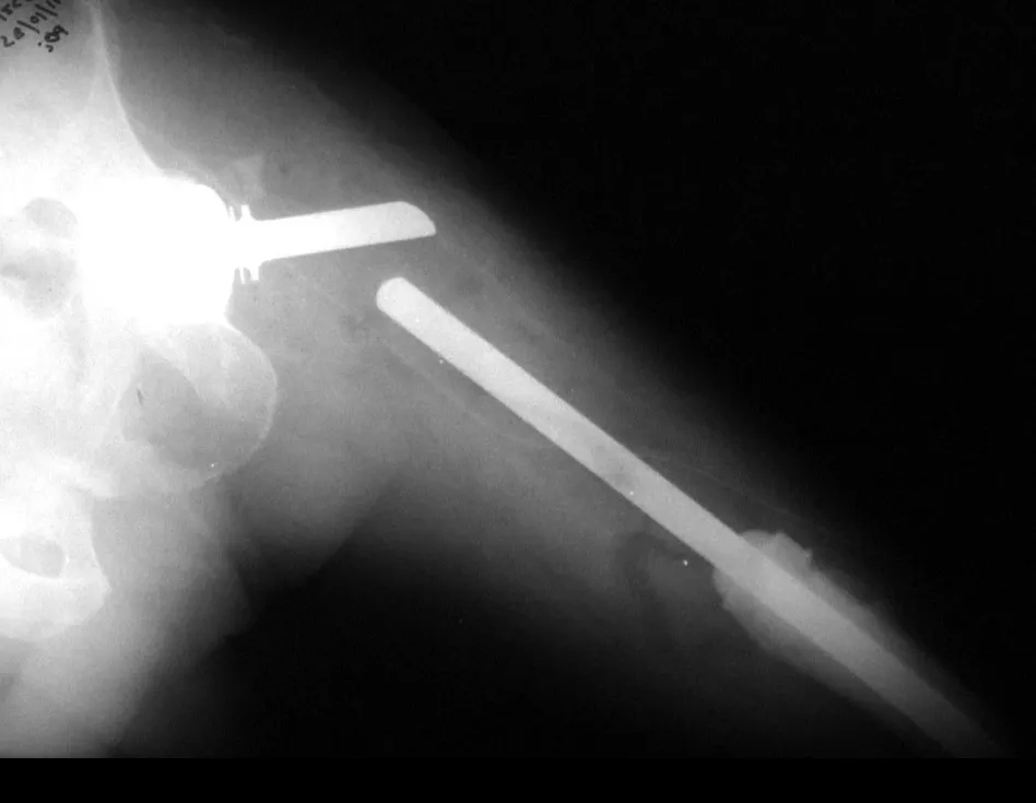
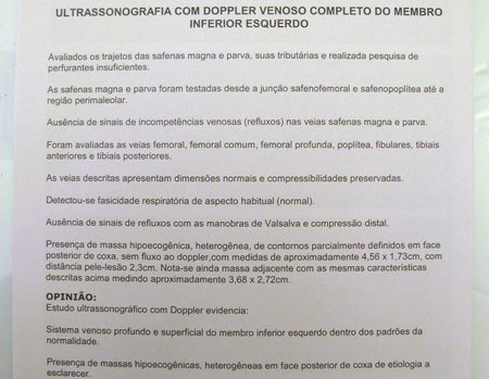
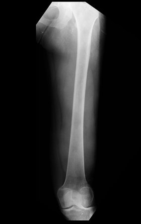
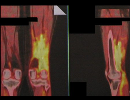
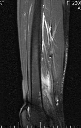
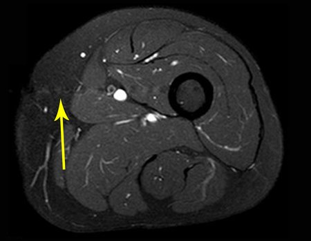
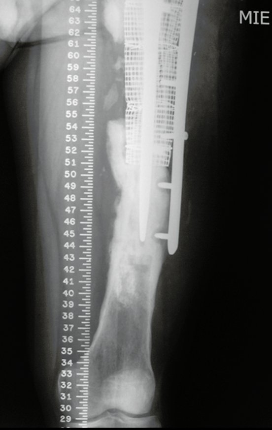
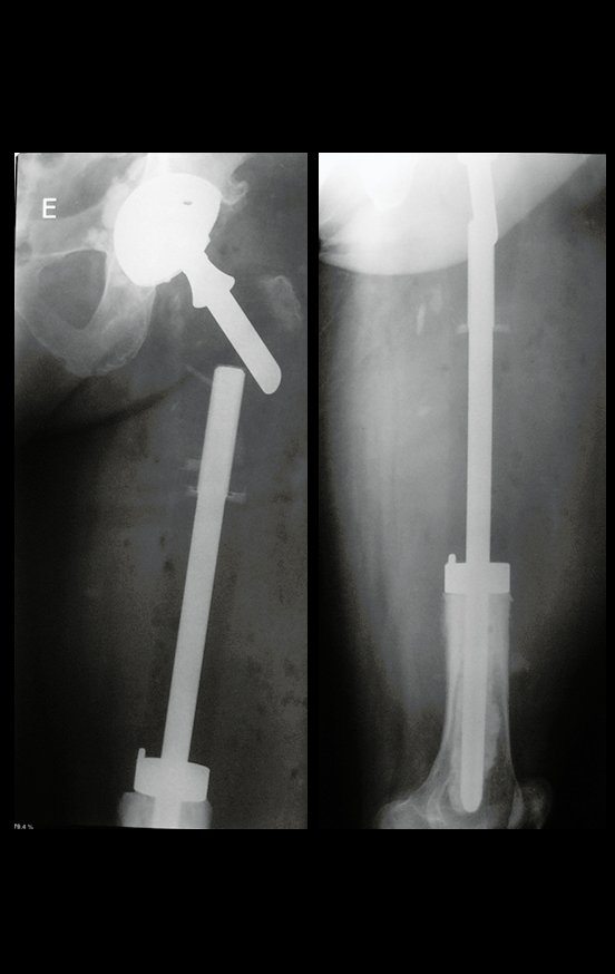
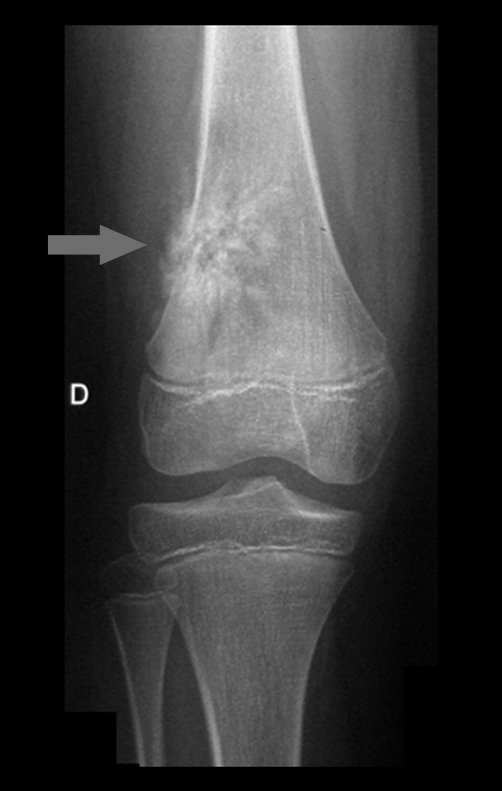
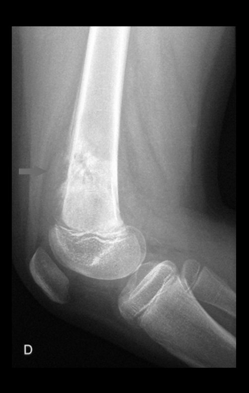
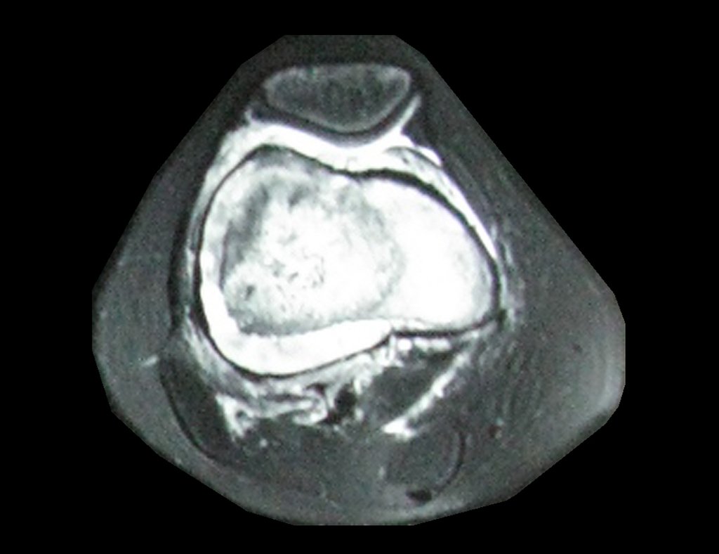
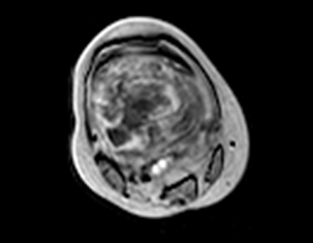
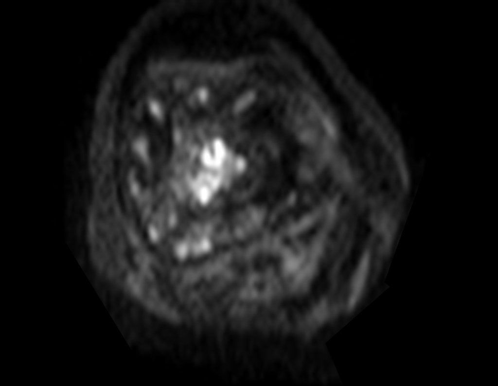
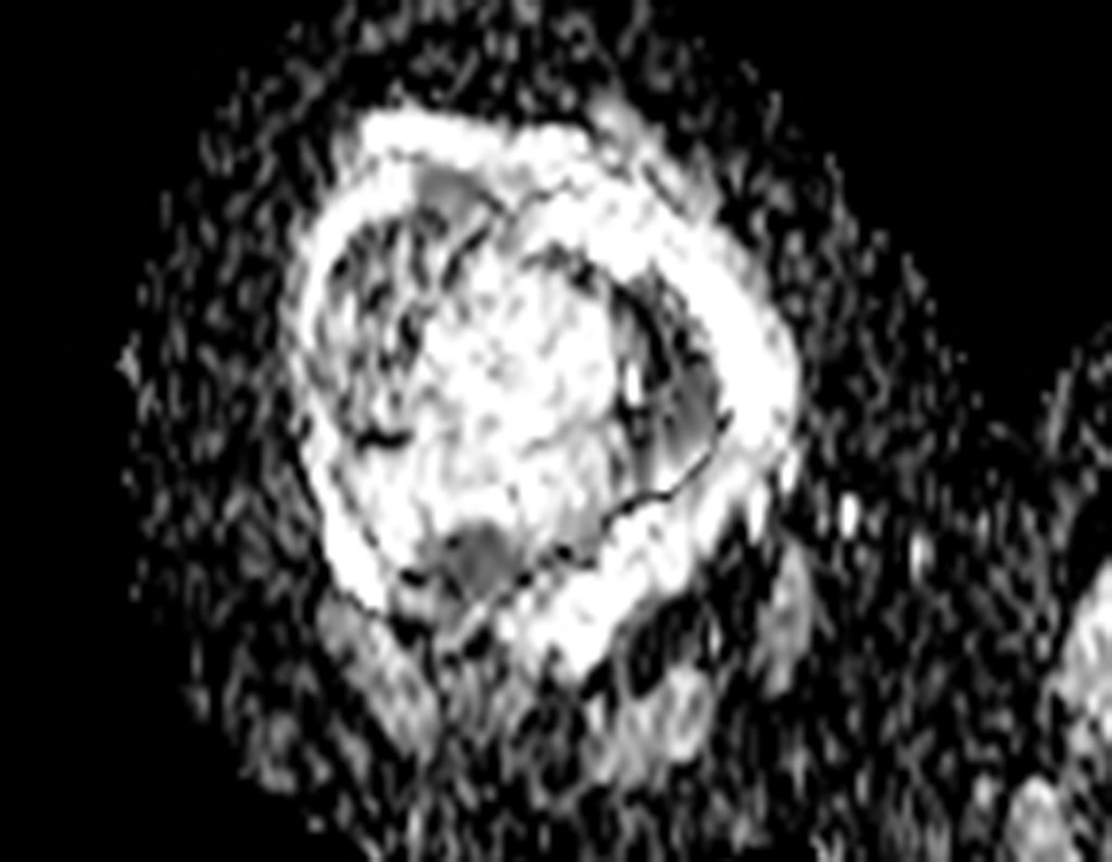
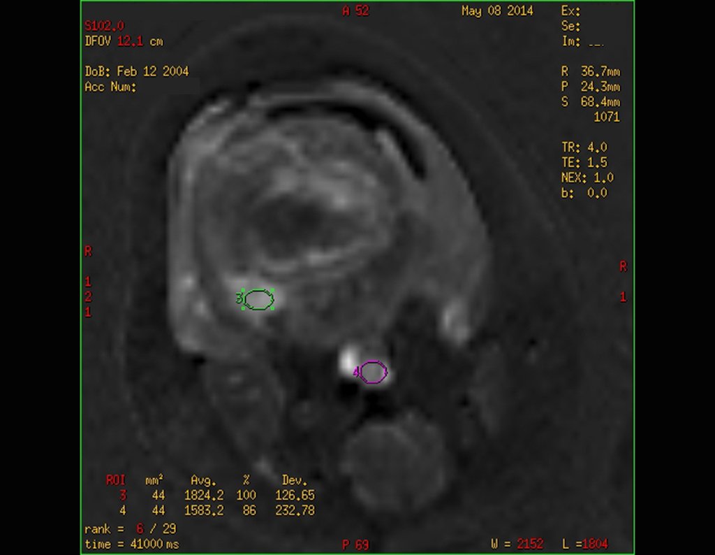
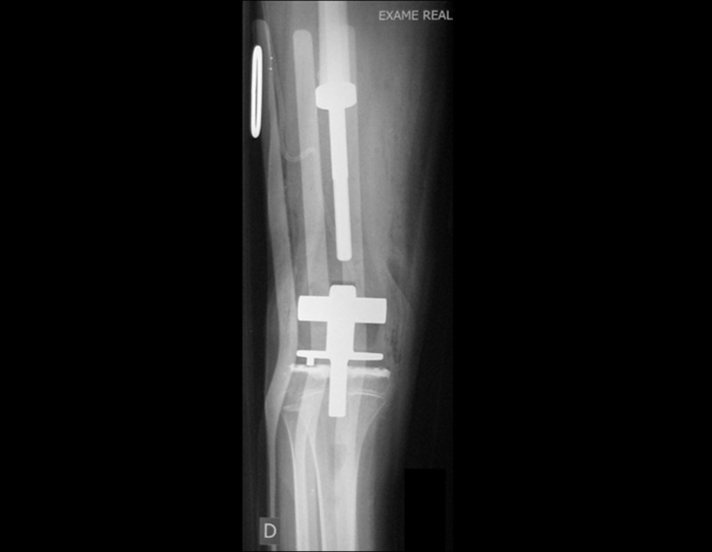
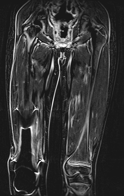
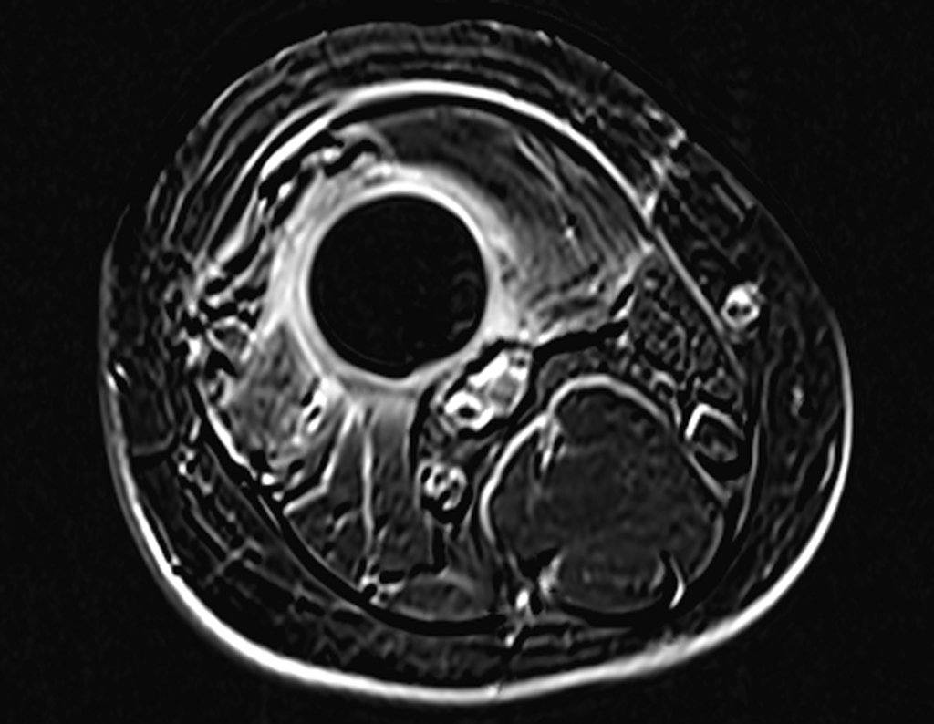
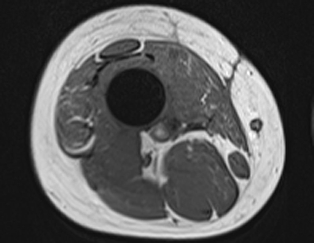
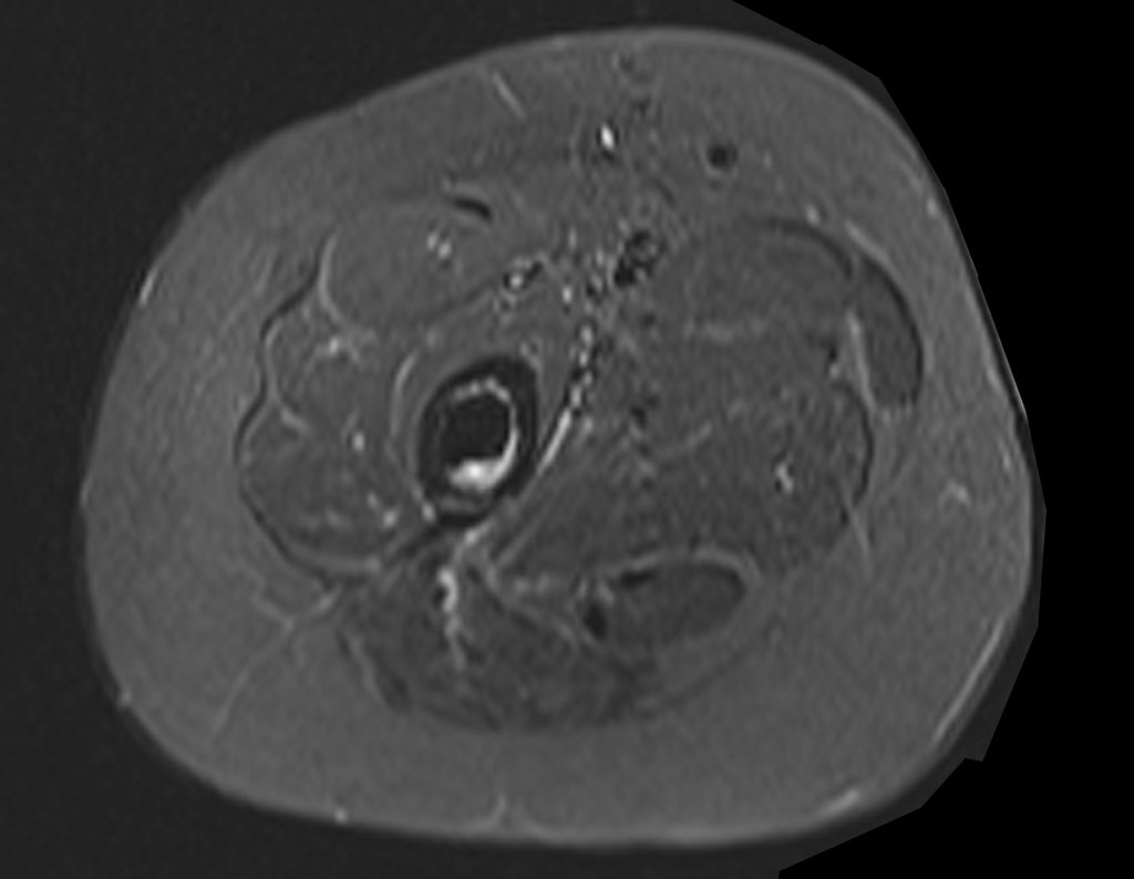
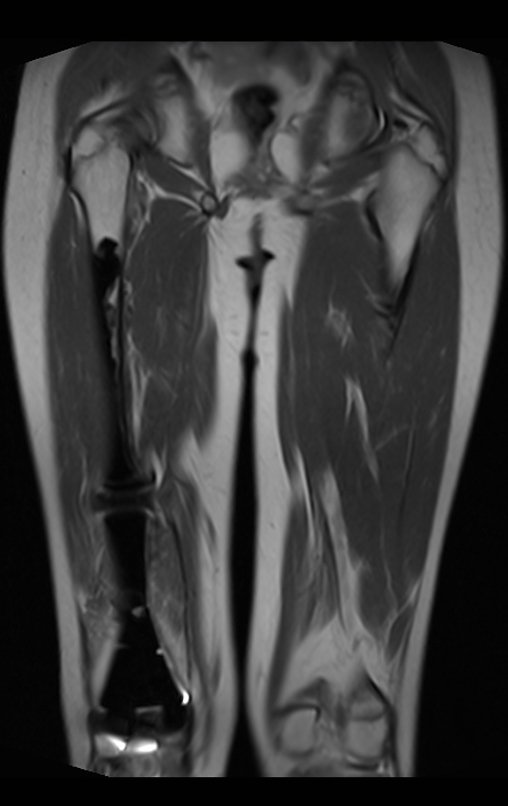
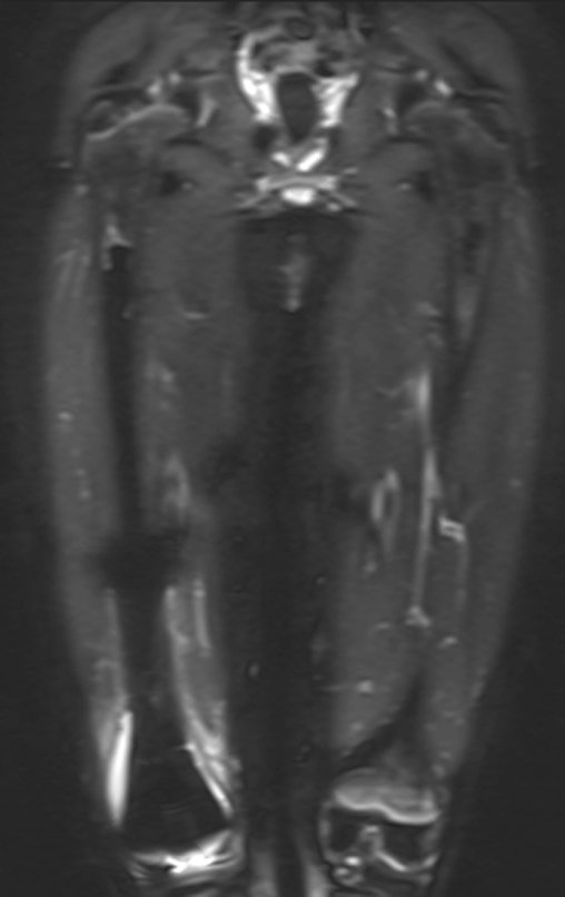
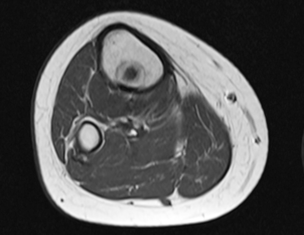
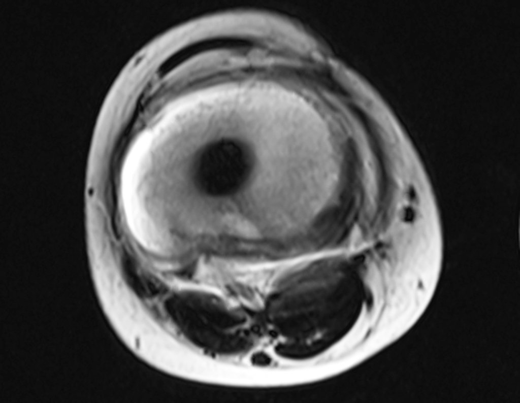
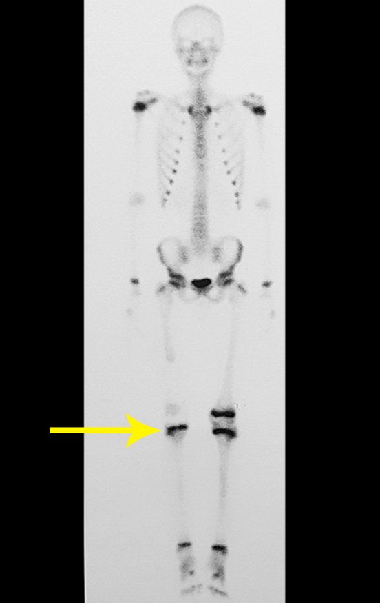
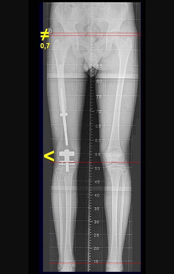
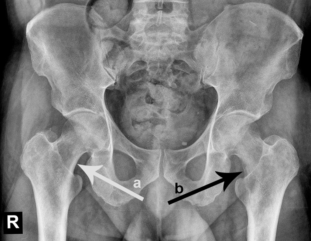
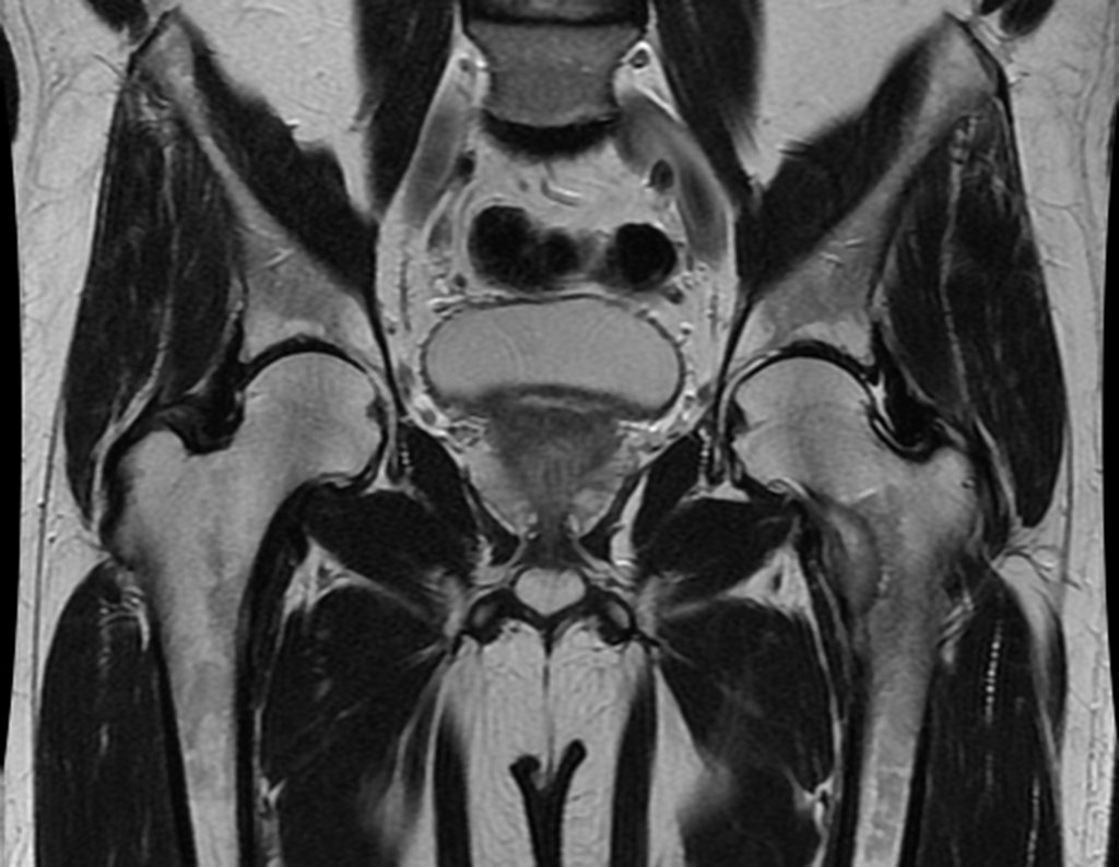
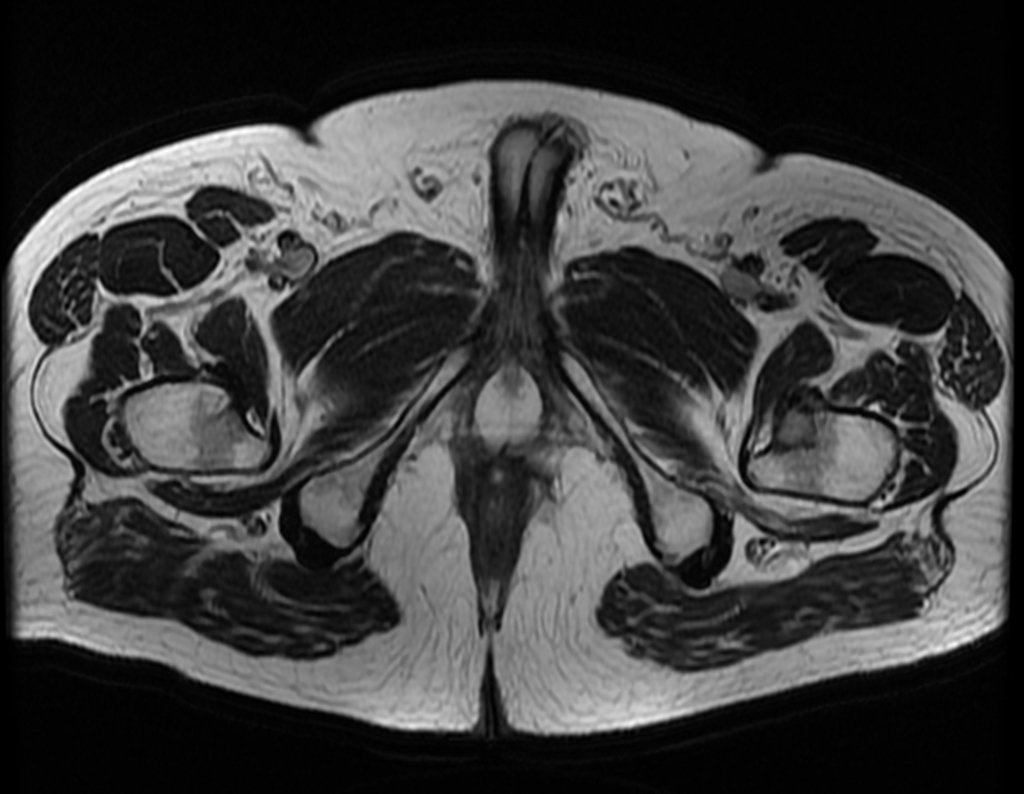
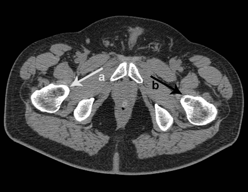
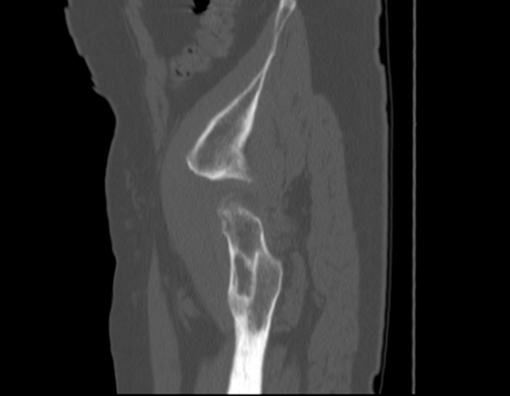
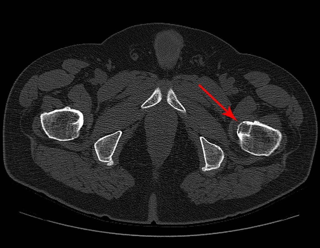
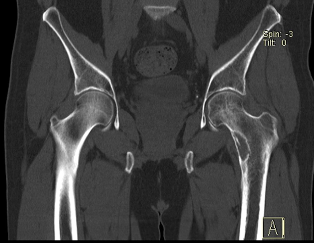
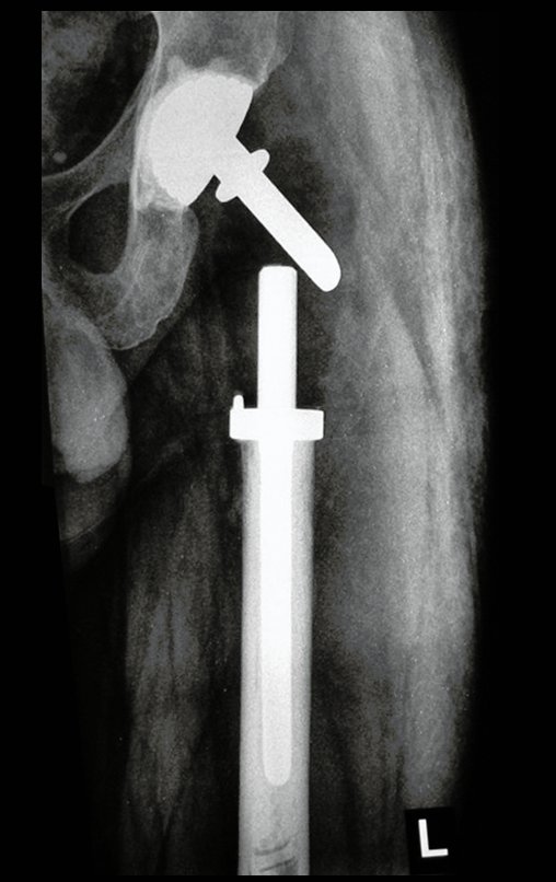
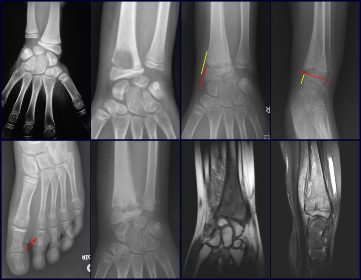
Imaging tests:  The radiographic image is of bone rarefaction, rounded or oval, which begins in the medullary bone and progresses with erosion of the cortical bone.

In the initial phase, the edges are irregular and poorly defined.

In the late phase, slight sclerosis may occur around the lesion. In long bones, there is an evident periosteal reaction that appears as multiple thick lamellar layers, which characterizes slow-evolving benign lesions or the reaction of osteomyelitis.

This type of solid periosteal reaction differentiates Eosinophilic Granuloma from Ewing’s Sarcoma, where the periosteal reaction is thin lamellar, due to the rapid evolution of the malignant tumor.

Another radiographic difference between these two lesions is that Ewing’s tumor early presents extra-cortical tumor tissue, with a large volume, which does not occur in Eosinophilic Granuloma.

In flat bones, such as the skull or pelvis, erosion affects both cortices in an irregular and asymmetrical manner, producing the visual impression of a hole within another hole, called a double contour lesion.

In the mandible, destruction of the alveolar bone produces the radiographic impression of floating teeth.

In the spine, the disease affects the vertebral body, with flattening occurring in 15% of cases, producing the so-called flat vertebra of Calvè6. The posterior elements and intervertebral discs are preserved, even when the injury occurs in more than one vertebra.
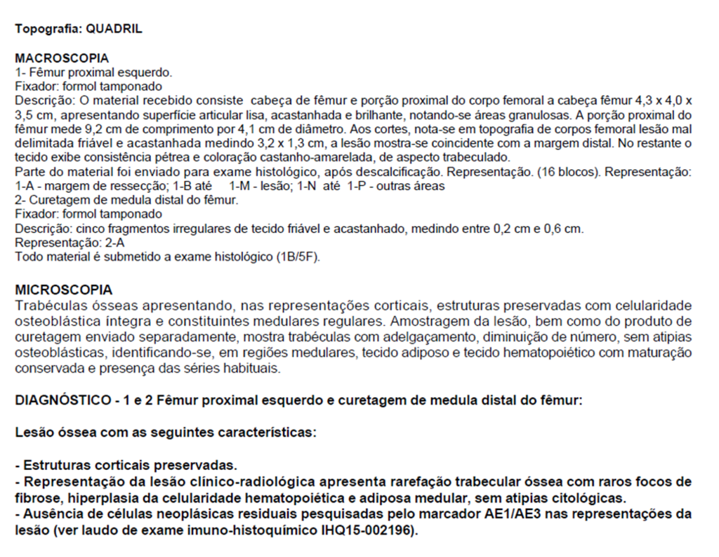
Pathologic anatomy:

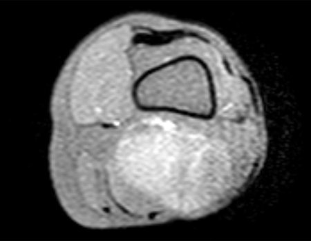
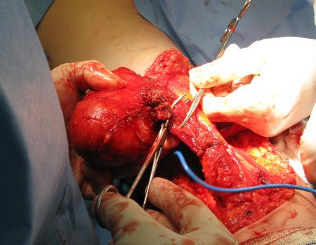
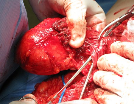
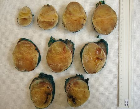
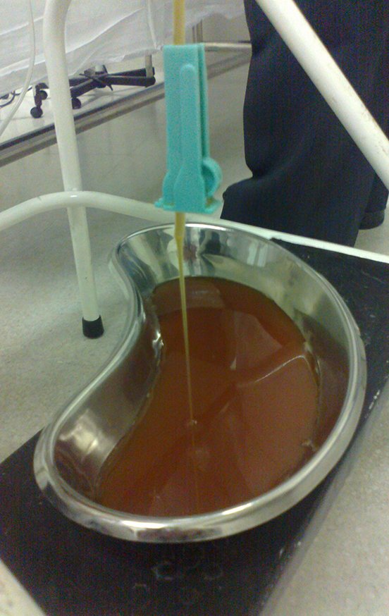
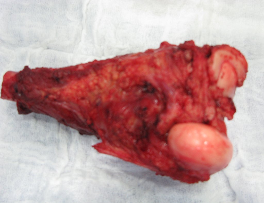
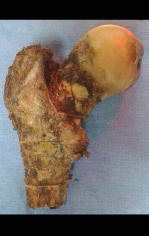
Macroscopic appearance:  it has a soft, gelatinous consistency, yellowish in color, necrotic liquefaction is common.

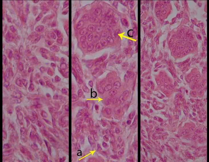
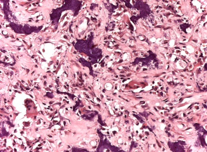
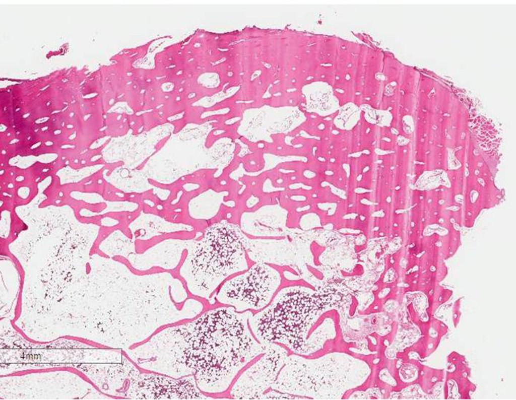
Microscopic appearance:  They appear as clusters of large histiocytic cells, with a slightly basophilic cytoplasm, globose, lobulated or indented nucleoli, in these cases similar to a bean seed, which correspond to Langerhans cells.

These clusters are interspersed with giant cells, lymphocytes, numerous eosinophils and areas of necrosis, simulating an abscess. Electron microscopy presents typical cytoplasmic granules called Birbeck bodies11,12.

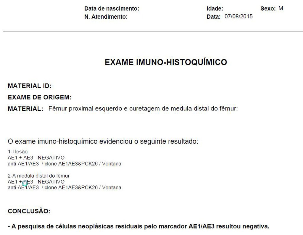
Immunohistochemistry shows positivity for S-100 protein, vimentin and CD1a11,13.

Diagnosis:

Differential diagnosis:  The main radiological differential diagnoses of Eosinophilic Granuloma are Osteomyelitis and Ewing Tumor.

When the lesion occurs in the skull, it must be differentiated from an epidermoid cyst or metastasis. The main histological differential diagnoses are Osteomyelitis and Lymphoma.

Staging:

Treatment:  The literature presents reports that expectant treatment or biopsy alone can be indicated as an effective therapeutic strategy for isolated skeletal injuries7,14.

Eosionophilic Granuloma can resolve spontaneously, especially in children. The capacity for the affected bone to rebuild itself exists, as the majority of patients are affected before skeletal maturity, therefore with great potential for remodeling by the growth physes, which are normally not affected15,16.

In our experience, there was resolution in five cases, which regressed only with percutaneous biopsy. The same happens after vertebral collapse in spinal injuries, probably due to the leakage of the contents of the lesion, resembling the drainage of an abscess, with surgical indication in the spine being extremely rare. Cases have been reported where there was complete restitution of the height of the vertebral body15. In our series we had two cases that presented this evolution.

Although there may be spontaneous resolution, the time required is unpredictable, and there may be significant morbidity secondary to intense pain and functional limitation.

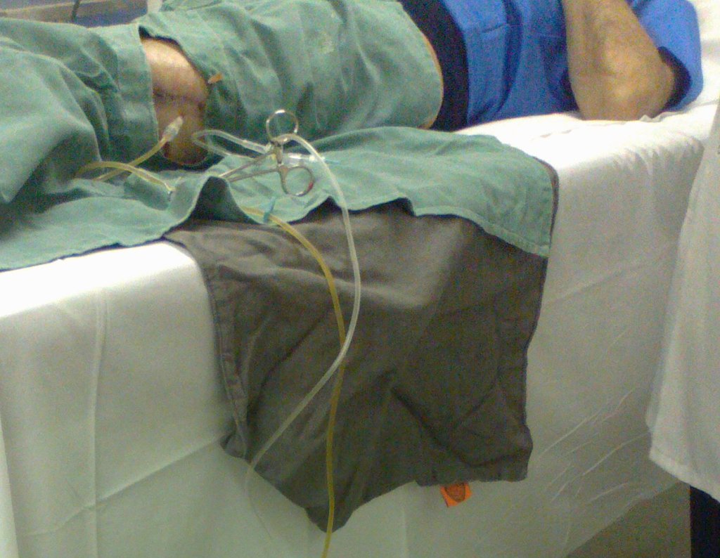
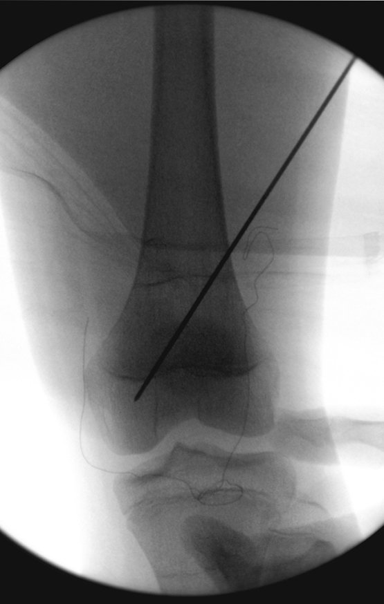
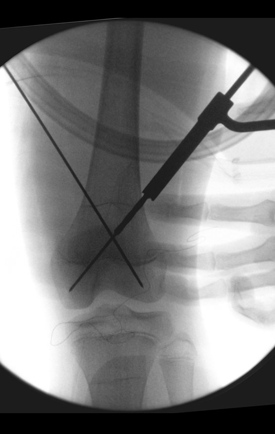
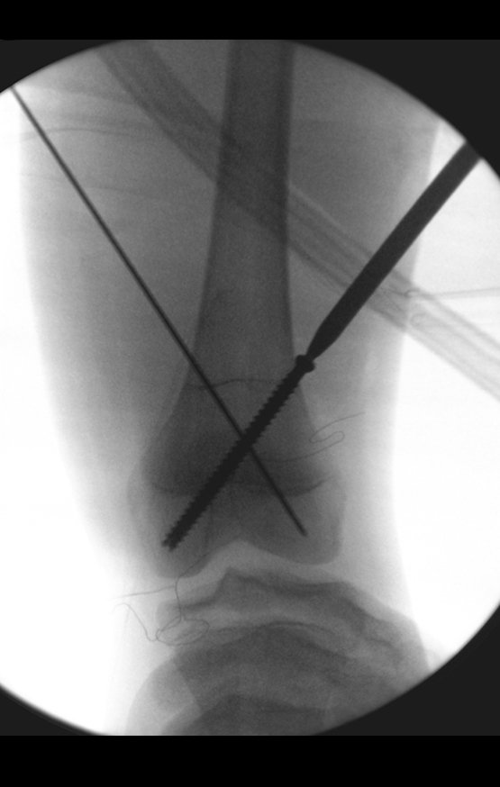
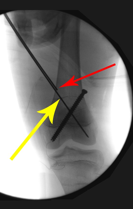
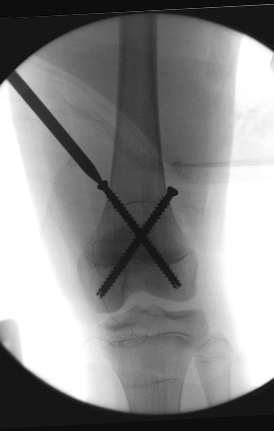
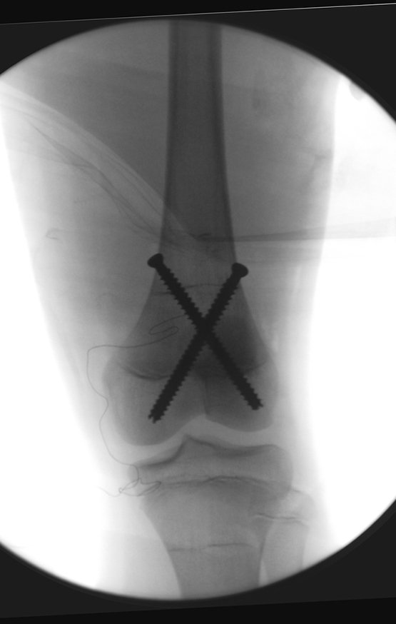
Currently, the best therapeutic approach for Eosionophilic Granuloma is to perform a percutaneous biopsy, if possible with immediate diagnosis by frozen section, followed by intralesional corticosteroid infusion (methylpredinisolone – 40mg to 120mg depending on the size of the lesion)7. The anatomopathological result must be subsequently confirmed by histology in paraffin blocks.

Eosionophilic Granuloma can take up to three months to regress, and it may be necessary to repeat the infusion6. In our experience, we had only one case, of an isolated injury to the humerus, which required complementation of the initial treatment in which we performed oral corticosteroid therapy, prednisolone 5mg/24h, for four months. In polyostotic Eosinophilic Granuloma, systemic corticosteroid therapy is used.

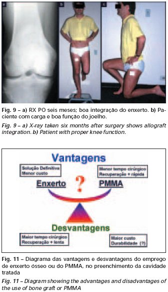
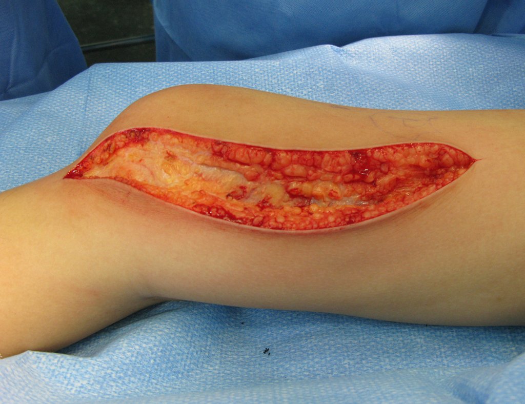
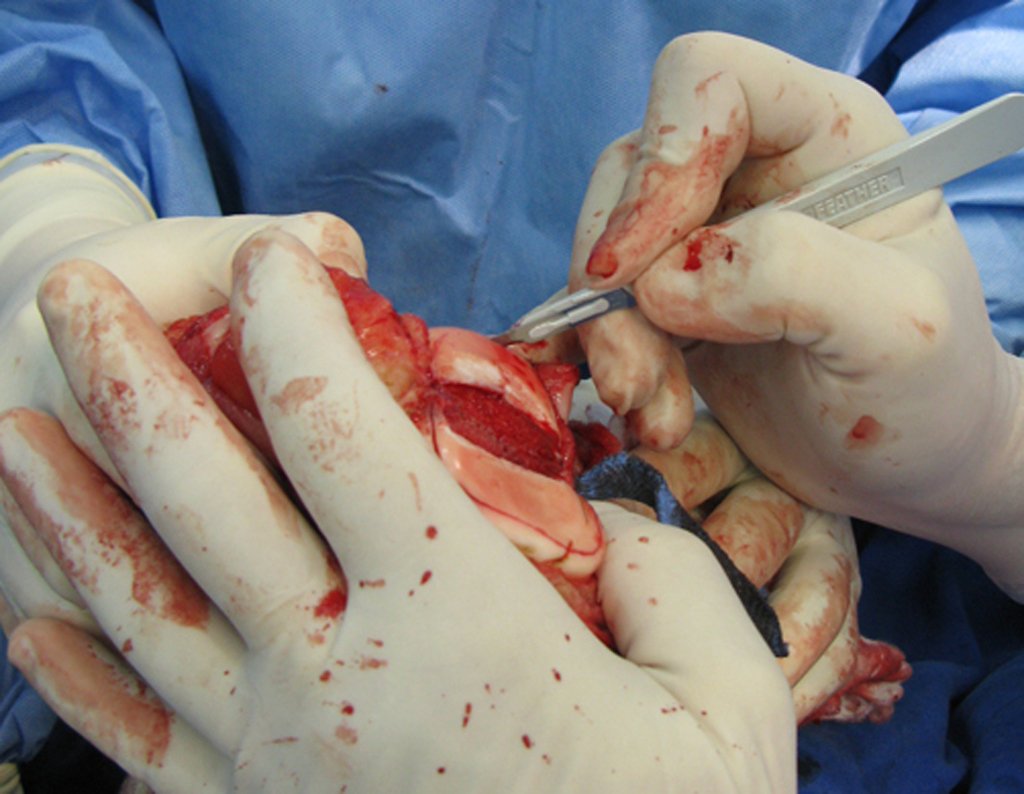
When an incisional biopsy is necessary, corticosteroids can be applied locally after curettage of the lesion, which facilitates the resolution of the process. This curettage must be careful, carried out by opening in the form of a narrow slit, longitudinal to the bone, trying not to add greater local fragility. Eventually, the cavity can be filled with a bone graft, but this is generally unnecessary due to the great potential for regeneration that exists.

Radiofrequency was proposed as a percutaneous treatment for Eosionophilic Granuloma, being applied in a second stage, two to four weeks after the biopsy17. The author restricts the technique to small injuries that are at least one centimeter away from the neural or visceral structures, warning of the risk of fractures in the load-bearing limbs. This approach, in addition to increasing costs and causing local morbidity, does not add any advantage to the treatment. The biopsy itself may have been curative, and the infusion of corticosteroids has greater justification, as this is indicated both in isolated cases and in multiple lesions. To date, there are no studies comparing percutaneous techniques with corticosteroid infusion in relation to the use of radiofrequency that justify their use. 

Historically, radiotherapy was used in low and fractionated doses for the treatment of Langerhans Cell Histiocytosis. Currently, the indication of radiotherapy for benign lesions is controversial.

In cases of eosinophilic granuloma with more than one skeletal lesion, without visceral involvement, systemic treatment may be indicated for a period of approximately six weeks with corticosteroid therapy (2 mg/kg) and Vinblastine (6 mg/kg).

Prognosis:  Solitary lesions of eosinophilic granuloma evolve well in 97% of cases, with biopsy alone or in addition to corticosteroid infusion or surgical treatment  . 

       See also:   Eosinophilic granuloma of the radius


Bibliography:

1 SCHAIRER, E. Ueber eine eigenartige Erkrankung des kindlichen Schädels.  Zentralbl Allg Patho Pathol. Anat., 71:113, 1938.

2 Otani S, Ehrlich JC; Solitary granuloma of bone simulating primary neoplasm. Am J Pathol 16:479–90. 1940

3 Green WT, Faber S; “eosinophilic or solitary granuloma” of bone. J Bone Joint Surg (Am) 24:499-526. 1942

4 Jaffe HL, Lichtenstein L; Eosinophilic granuloma of bone. Arch Pathol 37: 99-118. 1944.

5 Lichtenstein L.: Histiocytosis Pathol. 56:84, 1953

6 Schwartz HS.  Orthopedic Knowledge Update: Musculoskeletal Tumors 2. American Academy of orthopedic Surgeons, Rosemont, Illinois. Chapter 12 (128-32), 2007

7 Mavrogenis AF, Abati CN, Bosco G, Ruggieri P. Intralesional Methylprednisolone for Painful Solitary Eosinophilic Granuloma of the Appendicular Skeleton in Children. J PediatrOrthop 2012;32:416–422

8 Chadha M, Agarwal A, Agarwal N, et al. Solitary eosinophilic granuloma of the radius. An unusual differential diagnosis. Acta Orthop Belg. 2007; 73:413–417.

9 Campanacci, M. Bone and Soft Tissue Tumors; Springer-Verlag Wien New York. Second Edition, (54); 857-75. 1999.

10 SCHAJOWICZ, F. Buenos Aires: Osseous Tumors; Talleres de editorial Médica Panamericana SA (9); 464-80. 1981.                  

11 CHRISTIAN, HA Defects in membranous bones, exosphthalmos and diabetes insipidus: in a usual syndrome of dyspituitarism: a clinical study.  Med.Clin. North. Am.,  3:849, 1920.

12 ARCECI, RJ; BRENNER, M.K.; PRITCHARD, J. Controversies and new approaches to the treatment of Langerhans cell histiocytosis.  Hemtol. Oncol. Clinic. North. Am., 12:339, 1998

13 ALBRIGHT, F.; REIFNSTEIN, EC  The parathyroid glands and metabolic disease.  Baltmore, Williams & Wilkins, 1948.

14 Plasschaert F, Craig C, Bell R, et al. Eosinophilic granuloma. A different behavior in children than in adults. J Bone Joint Surg Br 2002;84:870–872.

15 Greenlee JD, Fenoy AJ, Donovan KA, et al. Eosinophilic granuloma in the pediatric spine. Pediatr Neurosurg. 2007; 43:285–292.

16 Sessa S, Sommelet D, Lascombes P, et al. Treatment of Langerhans cell histiocytosis in children. Experience at the Children’s Hospital of Nancy. J Bone Joint Surg Am. 1994; 76:1513–1525.

17 Corby RR, Stacy GS, Peabody TD, et al. Radiofrequency ablation of solitary eosinophilic granuloma of bone. Am J Roentgenol.2008;190:1492–1494.

Author: Prof. Dr. Pedro Péricles Ribeiro Baptista

 Orthopedic Oncosurgery at the Dr. Arnaldo Vieira de Carvalho Cancer Institute

4a9f57c5dadf5bc6555a2e754ca3cfa7 3

Post-Operative Infection

[auto_translate_button]
Post-Operative Infection. Objective: To carry out a retrospective analysis of cases submitted to orthopedic damage control in a teaching hospital orthopedic emergency room with the aim of evaluating patients with postoperative infection after being converted to internal osteosynthesis. Methods: Retrospective analysis of patients from June 2012 to June 2013 undergoing orthopedic damage control with an external fixator that were later converted to definitive osteosynthesis, with a rod or plate. Results: We found an infection rate of 13.3% in our sample and verified technical errors in the preparation of the fixator in 60.4% of opportunities.Conclusion: An infection rate was found that we consider high, as well as inadequacies in the construction of the external fixator. We emphasize that this procedure is not without risk and training for doctors who perform it must be mandatory.

Postoperative infection in patients undergoing orthopedic damage control using external fixation

a Department of Orthopedics, Santa Casa de São Paulo, São Paulo, SP, Brazil
b Orthopedics and Traumatology Service, Hospital Israelita Albert Einstein, Federal University of São Paulo (Unifesp), São Paulo, SP, Brazil
c Institute of Orthopedics, Hospital das Clínicas, Faculty of Medicine, University of São Paulo (USP), São Paulo, SP, Brazil
d Escola Paulista de Medicina, Universidade Federal de São Paulo (Unifesp), São Paulo, SP, Brazil

Introduction

Damage control in orthopedics is a surgical tactic recommended for polytraumatized patients or those with severe soft tissue injuries, as recognized in the literature.1However, this procedure is not without risks. Local and systemic complications associated with external fixation for damage control2 have been reported, and one of them is bone infection. Studies show infection rates in pin tracts ranging from 0.5 to 30%.

Bacterial contamination and infection in the path of external fixator pins are relatively common and conversion to internal osteosynthesis, whether with intramedullary nails or plates, in the presence of such a condition, can lead to serious complications, local and/or systemic.4The frequency of this association of events is not clear in the literature.

The correlation between infection in the path of external fixator pins and post-traumatic osteomyelitis after internal osteosynthesis, which constitutes chronic infection of the locomotor system, is well established.

Infection at the bone-fixator pin interface has been proven to be directly associated with the insertion technique, stability and position in the limb, during pin placement, by establishing tension or not in the soft parts. The presence of these factors contributes to infectious complications after conversion to definitive internal osteosynthesis, whether intramedullary nail or plate.

The objective of our work is to identify in patients undergoing control of musculoskeletal damage admitted to the emergency room for one year, the quality of reduction and fixation and the frequency of bone infection after definitive treatment.

Casuistry and methods

This work was duly submitted to and approved by the institution’s Ethics Committee and is registered under protocol CEP no. 624.307.

We retrospectively evaluated 120 patients who underwent external fixation to control musculoskeletal damage from June 2012 to June 2013 and were treated at the time of emergency in the emergency room of the Department of Orthopedics and Traumatology at our institution.

In this retrospective study, we included patients who underwent damage control surgery using external fixation that

after conversion to definitive osteosynthesis, they developed infection.

Patients who presented infectious complications due to local systemic changes, such as vasculopathies, diabetes mellitus or consumptive disease, and patients with psychiatric disorders that may have impaired the development or care of the fixator in any way were excluded.

All radiographs were generated in digital form and analyzed using the Impax program. The distances between Schanz holes and pins until the definitive synthesis were analyzed in the program itself. We sought to identify the presence of technical errors during drilling (characterized by multiple perforations) or subjective analysis carried out by three different groups of two evaluators. One group was made up of assistant doctors with at least five years of experience in orthopedic trauma, another with two third-year residents and another with two second-year orthopedic residents. The evaluators were named (table 1):

Tabela 1
Tabela 1

– Evaluator 1: assistant with more than five years of experience

– Evaluator 2: assistant with more than five years of experience

– Evaluator 3: third year resident

– Evaluator 4: third year resident

– Evaluator 5: second year resident

– Evaluator 6: second year resident

Postoperative infection was characterized by clinical examination, during hospitalization or during outpatient investigation, based on data recorded in the medical records. The following clinical criteria for infection were considered: erythema, hyperemia or fistula in the path of the pins or surgical incision (fig. 1).

During external fixation, prior drilling with a drill and manual insertion of the pins were always respected.

Figura 1.
Figure 1.

In no case did we have a pin in the fracture exposure zone.

In evaluating the radiographs, we observed the pre- and post-operative exams, we measured the position and distance of the Schanz pins in relation to the definitive synthesis, the presence of perforations in a greater number than the pins installed as this suggests difficulty and additional damage in installing the external fixator, presence of osteolysis in the holes for the Schanz pins and if the place where the pins were drilled caused problems for definitive internal fixation. Among these, we evidence postponed surgery due to infection in the pin path, changes in the surgical incision for definitive osteosynthesis and unplanned surgical procedures for reassembly of the fixator due to unstable assembly.

The average conversion time from external fixators to definitive osteosynthesis was evaluated by retrospective analysis of medical records.

Results

Of the 120 patients who underwent damage control, 16 (13.3%) suffered post-traumatic osteomyelitis after definitive synthesis. In these 16 patients, we were able to directly relate it to definitive internal osteosynthesis, as there were no signs of local infection after external fixation in the urgency.

The average age of these 16 patients was 43.4 years, ranging from 19 to 81. We observed a predominance of males, with 13 patients (81.2%), and the remaining three (18.8%) females.

Regarding the external fixator conversion time for definitive osteosynthesis, the shortest period was five days and the longest was 30. We had an average of 15 days for the final conversion.

Infection occurred in eight isolated leg fractures (50%), two patients with fractures of the femur and ipsilateral tibia (floating knee), two (12.5%) with ankle fractures (12.5%), two (12.5%) %) with a tibial plateau fracture, one (6.2%) with an isolated femur fracture and one (6.2%) with a humeral fracture.

Of the 16 patients with post-traumatic infection, 37.5% of the time (six patients) occurred after closed fractures and in 62.5% (10) after Gustillo grade 3 A open fractures (table 2).

In 62.5% (10 patients) the fixator was mounted transarticularly and in the remaining six (37.5%) it was monostolic with monolateral configuration, with tube-to-tube connection.

As for the etiological agent, it was adequately identified in 10 patients (62.5%) of the 16 infected, in a third of these there were multiple bacteria and there was a need for surgery to clean, debridement and curettage of the pin hole path. The polymicrobial findings found in intraoperative cultures were: Staphylococcus aureus, coagulase-negative Staphylococcus, Klebsiella sp, Acinetobacterbaumanni and Pseudomonas aeruginosa.

Regarding the objective assessment of multiple bone perforations, we observed a greater number than pins used in eight patients (50%) of the 16 patients infected after definitive osteosynthesis (fig. 2).

Figura 2
Figure 2

When we measured the distance between the position of the Schanz pin and that of the osteosynthesis, we obtained an average of 2.2 cm, with a variation of up to 6 cm. In seven cases (43.8%) of the 16 infected people, the distance measured was 0 cm, two between 1 and 2 cm, two between 3 and 4 cm, one between 4 and 5 cm, three with 5 cm and one with 6 cm (table 2). Regarding the evaluation of the quality of fixation and reduction, we were able to observe that of the 16 cases, in four (25%) the six evaluators agreed, in two the fixation was considered adequate and in the other two inadequate; in five cases (31.3%) five evaluators agreed on the quality of the evaluation, in two it was considered adequate and in three inadequate; in four cases (25%) four evaluators agreed with the evaluation, all were considered inadequate; In three cases (18.7%) there was no agreement between the evaluators, three considered the fixation and reduction to be adequate and three others to be inadequate (table 3).

In the 13 cases (81.2%) in which there was some agreement (adequate or inadequate), it was considered adequate in four (30.8%) and inadequate in nine (69.2%).

When analyzing the evaluations, we obtained 96 evaluations, which were considered adequate in 38 cases (39.6%) and inadequate in 58 cases (60.4%). When analyzing the evaluations of each evaluator, we obtained for evaluator one: five cases (31.3%) evaluated as adequate and 11 (68.7%) as inadequate; assessor two: 10 cases

When we separately evaluated orthopedists with more than five years of experience, we obtained 32 evaluations, 15 (46.9%) were considered adequate and 17 (53.1%) were considered inadequate (table 4). In this group, there was agreement in the quality of fixation and reduction in nine cases (56.3%) and non-agreement in the remaining seven (43.7%), of the nine cases with agreement in four (44.4%). ) the quality of reduction and fixation was considered adequate and in five (55.6%) inadequate.

When we evaluated third-year residents separately, we obtained 32 evaluations, 14 evaluations (43.7%) were considered adequate and 18 (56.3%) were considered inadequate (table 4). In this group, there was agreement on the quality of reduction and fixation in nine cases (56 .3%) and non-agreement in the remaining seven (43.7%), of the nine cases with agreement in four (44.4%) the reduction and fixation was considered adequate and in five (55.6%) inadequate.

When we evaluated second-year residents separately, we obtained 32 evaluations, nine (28.1%) were considered adequate and 23 (71.9%) were considered inadequate (table 4). In this group, there was agreement on the quality of reduction and fixation in 13 cases (81.3%) and non-agreement in the remaining three (18.7%), of the 13 cases with agreement in three (23.1%), reduction and fixation were considered adequate and in 10 (76.9%) inadequate.

When observing the assessments considered adequate, we can see a tendency towards similar assessments between assistants and third-year residents, but a lower assessment of cases considered suitable for second-year residents (table 5).

When we compared the cases in which the assistants agreed with the third-year residents’ assessment, we observed that there was agreement in five (31.3%) of the 16 cases, in three the reduction and fixation was considered adequate and in two inadequate. Of the remaining 11 cases, in four, despite the agreement of the assistants’ assessment, there was no agreement with the third-year residents; in one case, the reduction and fixation was considered adequate by the assistants and in three cases, inadequate.

When we compared the cases in which the assistants agreed with the assessment of the second-year residents, we observed that there was agreement in seven (77.8%) of the nine cases, in two of these the reduction and fixation was considered adequate and in five inadequate. In one case where there was agreement from the assistants (considered adequate) the second year residents considered it inadequate.

When evaluating the seven cases in which there was no agreement among assistants with more than five years of experience, we observed that in one case the residents, whether third or second year, also did not agree. In four cases, the two third-year resident evaluators also did not agree and in three cases the two third-year resident evaluators agreed and considered the reduction and fixation inadequate. Of the seven cases in which the assistants did not agree, the second-year resident evaluators considered the reduction and fixation adequate in one case and inadequate in four.

Discussion

External fixators, more versatile fixation devices that allow different types of assemblies and configurations, can be placed quickly, are applied in the treatment of fractures in urgent and emergency situations (damage control) and in a percutaneous, with less damage to soft tissues.

This procedure, both provisional and definitive, is still routine in many services and varies from 32 to 89% of the choice of a group of orthopedists in a previous study.9However, this procedure is not without risks.

In our sample, we found a frequency of 13.3% of infection after the use of an external fixator for damage control. Although compatible with literature data, which range from 0.5 to 30%,2,3 we are concerned with judging this rate very high among the possible complications.

The first issue always remembered when searching for the etiology of the infection is the environment in which the treatment takes place, in our case a teaching hospital. It seems like a weak cause-and-effect correlation, because the procedure is considered to be of little complexity and there was at least one doctor with three years of training on the surgical team.

Another factor that is involved in the complication of infection after internal osteosynthesis is infection of the Schanz pin tract. In our patients, the presence of clinical suspicion of infection was an indication to exchange the pin for installation in another location or to continue treatment with osteosynthesis using the external fixator.

Reduction and fixation were considered inadequate in 60% of evaluations, a value considered very high, and on average, assistants and third-year residents found reduction and fixation adequate in only 50% of evaluations. This shows that there is a need for better teaching in the treatment of emergency situations with external fixators.

External fixation is often neglected in our environment both in its preoperative planning, procedure and subsequent care. In any external fixation procedure, the future definitive synthesis must always be considered when assembling the fixator and placing the pins. This situation should always be discussed with the attending physician, who can make a pre-operative schedule with a view to future synthesis, whether plate or rod. In our study, in 43.8% of cases, the location of the Schanz pin was not far from the definitive osteosynthesis.

The correct technique for inserting the pin, care with the dressing and the surgical wound are essential to prevent these complications.9,10Pre-drilling, manual insertion of the pins, use of the safety corridor are factors that cannot be forgotten during the fixation. The systematization of this intra- and post-operative care is a factor that we found capable of control by the doctor to influence the infection rate of the Schanz pin path in damage control.

Routinely, the quality of fracture reduction is not so important to consider postoperative infection, since the use of the external fixator is temporary.8 However, in some situations in which the fixator remains in place for a prolonged time, this factor must be taken into account. In our series, the longest period for conversion was 30 days and the temporary reduction is important for stabilizing the condition, local care and general condition.

In our cases, we observed that all of them had a safety event respected in the analysis of the radiographs (in our case series, no neurovascular lesions were observed).

When we identified the importance of the quality of the installation and spatial assembly of external fixators, we asked doctors with different training periods to judge the quality of the assembly and look for signs of technical inadequacy in the x-rays in the files, which occurred 60% of the time in our study, value considered very high.

Regarding the frequency of bone infection post-damage control, we confirmed that of the 13% infected, 50% identified the presence of error or technical inadequacy that may have contributed to the undesirable outcome./p>

When considering external fixator assemblies, we cannot correlate the frequency of infection with a given type of assemblage. There was a prevalence of transarticular assemblies, used in metaepiphyseal fractures, ipsilateral bone fractures and extensive soft tissue injuries to avoid post-traumatic joint deformities (62.5% of cases).

Although it was not possible to correlate infection after internal osteosynthesis and the use of fixators to control damage, the presence of inadequacy in assemblies in the emergency room suggests the possibility and need for training and rules for their use and assembly.

Conclusion

Bone infection occurred in 13.3% of cases treated with control of musculoskeletal damage after internal osteosynthesis. In these cases, reduction and fixation was considered adequate in 39.6% of evaluations and inadequate in 60.4%. We emphasize that this procedure is not without risk and training for doctors who perform it must be mandatory.

Interest conflicts

The authors declare no conflicts of interest.

Interest conflicts

The authors declare no conflicts of interest.

REFERENCES

1. Scalea TM, Boswell SA, Scott JD, Mitchell KA, Kramer ME, Pollak AN. External fixation as a bridge to intramedullarynailing for patients with multiple injuries and with femurfractures: damage control orthopedics. J Trauma.2000;48(4):613-21.2. Parameswaran AD, Roberts CS, Seligson D, Voor M. Pin tract infection with contemporary external fixation: how much of a problem? J Orthop Trauma. 2003;17(7):503-7.3. Mahan J, Seligson D, Henry SL, Hynes P, Dobbins J. Factors in pin tract infections. Orthopedics. 1991;14(3):305-8.4. Harwood PJ, Giannoudis PV, Probst C, Krettek C, Pape HC. The risk of local infectious complications after damage control procedures for femoral shaft fracture. J Orthop Trauma.2006;20(3):181-9.5. Green SA, Ripley MJ. Chronic osteomyelitis in pin tracks. JBone Joint Surg Am. 1984;66(7):1092-8.6. Clasper JC, Cannon LB, Stapley SA, Taylor VM, Watkins PE.Fluid accumulation and the rapid spread of bacteria in the pathogenesis of external fixator pin track infection. Injury.2001;32(5):377-81.7. Moroni A, Vannini F, Mosca M, Giannini S. State of the art review: techniques to avoid pin loosening and infection in external fixation. J Orthop Trauma. 2002;16(3):189-95.8. Cardozo RT, Silva LG, Bragante LA, Rocha MA. Treatment of tibial shaft fractures with an external fixator compared to a locked intramedullary nail. Rev Bras Ortop.2013;48(2):137-44.9. Balbachevsky D, Belloti JC, Martins CVE, Fernandes HJA, Faloppa F, Reis FB. How are open tibial fractures treated in Brazil? Cross-sectional study. Acta Ortop Bras.2005;13(5):229-32.10. Petinne KA, Chao EY, Kelly PJ. Analysis of the external fixatorpin-bone interface. Clin Orthop Relat Res 1993;293:18-27.

Click here to download the PDF


Author: Prof. Dr. Pedro Péricles Ribeiro Baptista

 Orthopedic Oncosurgery at the Dr. Arnaldo Vieira de Carvalho Cancer Institute

D473d250193acc1cb049f2840310c2c4 3

Metastasis in the femur

[auto_translate_button]
Metastasis in the femur from male breast carcinoma. The authors report a case of pathological fracture due to bone metastasis from male breast carcinoma. The patient in question had a breast lump on the right with a history of six years, undiagnosed when treated for a femur fracture eight months ago. The importance of a complete and careful physical examination is highlighted in this work. This will avoid making a late diagnosis of neoplasia and bone metastasis. The importance of thinking about breast cancer in patients with pathological fractures is highlighted, even if they are men. The case is presented because it is a rare disease in humans. General aspects of the treatment of bone metastases are mentioned.

Metastasis in the femur from male breast carcinoma

INTRODUCTION

Breast cancer is a neoplasm that most frequently originates from the excretory ducts of the gland and also from its acini. It occupies a prominent place as a cause
of death in women, but in men it is very rare. For every 100 cases of breast cancer, only one is male. It affects the adult age group, generally over 50 years old. Due to the scarcity of breast parenchyma in men, cancer infiltrates more quickly and adheres to the skin with ulceration(3,5). It behaves exactly as in invasive ductal carcinomas in women, but generally presents with minor desmoplasia. The spread is the same as in women, with
early metastases in the axillary nodes. Metastases in the lungs, brain, bones and liver are also frequent, via the hematogenous route. The femur is the most affected bone(3). The objective of this work is to report a rare case of bone metastasis from male breast carcinoma, due to its rarity and propensity for misdiagnosis.

CASE REPORT

A 69-year-old male patient was admitted to the emergency room of the Department of Orthopedics and Traumatology of Santa Casa de São Paulo, with a history of
falling to the ground four hours ago, with pain and functional impotence of the right lower limb. At admission, shortening and deformity in external rotation of the right lower limb were observed
. At the time, no other abnormalities were noted on physical examination.
On radiographic examination, in the anteroposterior projection of the pelvis and lateral aspect of the right hip (Fig. 1), a long oblique fracture without comminution or other bone injury was observed in the subtrochanteric region of the right femur. Biochemical and hematological blood analyses, chest x-rays and electrocardiogram were normal. The patient underwent anatomical reduction and osteosynthesis of the fracture with a 95º angled plate (fig. 2).

Fig. 1 e 2 – Radiografias do fêmur proximal direito, com fratura, realizadas à admissão do paciente. Rx após osteossíntese
Fig. 1 and 2 – Radiographs of the right proximal femur, with fracture, taken upon patient admission. Rx after osteosynthesis
The patient evolved well in the immediate postoperative period, with no signs of infection or any other significant changes. After discharge, he began to be monitored monthly through clinical and radiographic examination. The radiographic controls apparently showed good evolution of the fracture (fig. 3, A and B), but, in the sixth postoperative month, the patient returned complaining of pain and a rapid and progressive increase in the volume of the thigh. Radiographs of the pelvis (antero-posterior) and right hip (lateral) (fig. 4, A and B) showed a lytic lesion at the level of the previously fractured area and loosening of the synthetic material.
Fig. 3 e 4 – Radiografias após 2 e 3 meses respectivamente.
Fig. 3 and 4 – Radiographs after 2 and 3 months respectively.
The patient was referred to the Musculoskeletal Tumor Group for case study. On this occasion, the presence of a tumor in the right breast measuring approximately 2.5 cm in diameter, with retraction of the nipple, which had not been previously detected (fig. 5, A and B), accompanied by lymph node involvement was noted. axillary. Upon rectal exam, there was an enlarged prostate with regular edges and a soft consistency, considered normal for his age. On orthopedic examination, the patient showed increased volume in the right thigh, pain on local palpation and a limping gait with the aid of crutches. The mobility of the right hip was: flexion of 100º, extension of –15º, abduction of 30º, adduction of 15º, external rotation of 60º and internal rotation of 0º. Neurological and vascular examinations were normal.
Fig. 5a e 5b – Quebra da plca. Realizada biópsia incisional do nódulo que o paciente apresentava na mama direita. O diagnóstico anatomopatológico foi de carcinoma ductal infiltrativo.
Fig. 5a and 5b – Breakage of the board. An incisional biopsy of the nodule in the patient's right breast was performed. The anatomopathological diagnosis was infiltrative ductal carcinoma.
Fig. 6 – Realizada ressecção tumoral e colocação de endoprótese não convencional de Fabroni com quadril articulado. Radiografia em projeção ântero-posterior.
Fig. 6 – Tumor resection and placement of a non-conventional Fabroni endoprosthesis with articulated hip were performed. Radiograph in anteroposterior projection.

The patient underwent a trocar biopsy of the lesion in the femur and an incisional biopsy of the mass in the breast. The results of the anatomopathological examinations were as follows: metastasis of adenocarcinoma in the femur and infiltrative ductal carcinoma of the breast. A resection of the proximal third of the right femur was performed and a non-conventional Fabroni endoprosthesis (ENCF) was placed (fig. 6). The evolution in the immediate postoperative period was satisfactory. Two weeks after surgery, the patient began chemotherapy with cyclophosphamide, fluoracil and farmorubicin with the aim of facilitating breast resection and lymph node emptying. Currently (six months post-operatively), the patient, still undergoing chemotherapy, has a limp with the aid of crutches, a normal neurological examination and the following mobility of the right hip: 90º of flexion,
–15º of extension, 30º of abduction , 20º of adduction, 60º of external rotation and 0º of internal rotation (fig. 5, A and B).

DISCUSSION

Male breast cancer, in addition to being rare, is highly aggressive, with early metastases to the axillary lymph nodes(5). According to a study carried out by Gallardo et al.(2) in 303 cases of bone metastasis due to breast cancer, it was found that only 1.33% were male patients.
No specific treatment for male breast carcinoma was found in the literature. The treatment for bone metastasis from breast cancer, when there is no imminent fracture, is essentially chemotherapy and radiotherapy. Sanoo et al.(7), using combined therapy with tamoxifen, cyclophosphamide, fluorocil, morphine and medroxyprogesterone 17-acetate, concluded that this chemotherapy was effective for bone pain in 96.33% of cases. Saez et al.(6) studied the survival of patients with breast cancer metastasis who underwent resection surgery, bone graft placement, chemotherapy and use of adjuvant antineoplastic agents. The study was carried out on 20 women between 24 and 56 years of age, of which nine had complete remission and 11 had partial remission. In our opinion, the use of bone grafts in metastatic tumors is highly debatable. The treatment of pathological fracture is varied. Some factors, such as age, stage of the primary disease, size of the metastasis and the patient’s general clinical impairment, influence the prognosis and help to choose the best treatment for the fracture(1). In patients with severe impairment of the general condition or large tumor extension, when surgical possibilities are very limited, treatment may be expectant(3). If the patient is ready to undergo surgery, the following can be performed: 1) reduction and osteosynthesis with a plate and bone cement aiming for a quick solution to the fracture, 2) resection of the lesion and placement of a non-conventional endoprosthesis, providing an early return to walking, and 3) amputation in extreme cases(1). We must remember the importance of carrying out a complete physical examination on all patients so that it does not go unnoticed, as in our case, a tumor in the breast that has been evolving for several years. A thorough physical examination, including in cases where there is no suspicion of a pathological fracture, can allow for an early diagnosis of the injury, improving the prognosis. We must also highlight the importance of including, in the differential diagnosis of bone lesions suggestive of metastasis in men, breast carcinoma as the primary tumor.

Click here to see a case of hypernephroma metastasis, treated before fracture.

REFERENCES

1. Carnelase, PG: “Malignant tumors of bone”, in Crenshaw, AH: Campbell’s operative orthopedics, St. Louis, Mosby Year Book, 1992. Chapter 10, p. 263-190.
2. Gallardo, H., Gonzales, R. & Astagno, A.: Osseous metastasis of breast cancer. Bol Acad Nal Med Nal 66: 459-471, 1988.
3. Campanacci, M.: Tumori delle ossa e delle parti molle, Bologna, Aulo Gaggi Editore, 1981. p. 456-512.
4. Pendleburg, SC, Bilous, M. & Langlands, SA: Sarcomas following radiation therapy for breast cancer: a report of three cases and a review of the literature. Int J Radiat Oncol Biol Phys 31: 405-410, 1995.
5. Robins, SL & Cotran, RS: “Mama”, in Structural and functional pathology, Rio de Janeiro, Interamericana, 1986. Chapter 27, p. 1158-1168.
6. Saez, RA, Slease, RB, Selby, GB et al: Long-term survival after autologous bone marrow transplantation for metastatic breast carcinoma. South Med J 88: 320-326, 1995.
7. Sanoo, H., Shimozuma, K., Kurebayashi, J. et al: Systemic therapeutic pain relief and quality of life of breast cancer patients with bone metastasis. Gan To Kagaku Ryoho 22 (Suppl): 10-15, 1995.

AUTHORS: PEDRO PÉRICLES RIBEIRO BAPTISTA, JOSÉ DONATO DE PROSPERO, FLORINDO VOLPE NETO, MARCOS SANMARTIN FERNANDEZ, NABIL ABISAMBRA PINILLA

Click here to download the PDF

Author: Prof. Dr. Pedro Péricles Ribeiro Baptista

 Orthopedic Oncosurgery at the Dr. Arnaldo Vieira de Carvalho Cancer Institute

36d838a7f08b7ac8295662b7b104440b 3

Giant Cell Tumor

[auto_translate_button]
Giant cell tumor is a neoplasm of mesenchymal nature, characterized by the proliferation of multinucleated giant cells (gigantocytes) that resemble osteoclasts, in a stroma of mononucleated cells (fig. 1a). It is also known as osteoclastoma and gigantocellular tumor, and the acronyms TCG or TGC are commonly used. It was first described by Sir Astley Cooper(1) in 1818. Later, Paget (1853)(2) called it “brown or myeloid tumor”. Nelaton (1860)(3) described its clinical and histological characteristics, highlighting its local aggressiveness and giving it the name “myeloplaxis tumor”. Gross (1879)(4) insisted on its benignity and highlighted the difficulties of differential diagnosis with “the aneurysmal variant of medullary sarcoma”. With the advent of radiology, the differential diagnosis of this lesion was determined and Bloodgood (1923)(5) proposed the name “benign giant cell tumor”.

Giant cell tumor

In recent decades, much has been discussed about the nature of gigantocellular tumors. For Geschikter and Copeland (1949)(6) and Willis (1949)(7), the gigantocellular tumor would be a neoplasm of osteoclasts in the mesenchymal stroma, given the similarity between the gigantocyte and the normal osteoclast.

Jaffe et al (1940)(8) described its origin as being derived from stromal cells. Sherman (1965)(9) stated that the bone disappeared at the site of tumor growth and the gigantocytes resulted from the fusion of stromal mesenchymal cells, taking into account the similarity between optical microscopy of stromal nuclei and giant cells. The histochemistry and tissue culture studies carried out by Schajowicz (1961)(10) did not demonstrate significant differences between tumor gigantocytes and normal osteoclasts. On the other hand, studies using electron microscopy(11) confirmed that giant cells are syncytia made up of stromal cells. Thus, the undifferentiated mesenchymal cells from the bone marrow would give rise to the tumor stroma, whose cells, in turn, when differentiating, would form clusters with the characteristics of gigantocytes. The numerous giant cells that resemble osteoclasts, in a stroma of spindle cells, are the most important elements of this tumor. The histological aspect of GCT presents characteristics common to several tumor and pseudotumor lesions(12,13), requiring joint analysis with clinical and imaging characteristics to confirm the diagnosis(14,15).

The main differential diagnoses, both from a clinical, radiographic and anatomopathological point of view, are: aneurysmal bone cyst, teleangectatic osteosarcoma and chondroblastoma(16,17). TGC generally affects a single bone. When a lesion suggestive of this tumor is found in several bones, the possibility of it being a “brown tumor of hyperparathyroidism” should be checked, which presents a similar radiographic appearance, but with multiple lesions and suggestive changes in serum calcium and phosphorus(18 ). GCT occurs in the third and fourth decades of life, affecting both sexes equally(19-22). The main manifestation is intermittent local pain, accompanied or not by an increase in volume in the affected region. The length of history is variable and depends on the bone and the affected region(23-26).
Some patients seek treatment due to pain, others because of the perception of the tumor or a pathological fracture(27,28). Generally, they relate the beginning of the clinical history to some trauma(29,30). As the tumor is epiphyseal, joint involvement with limited movement is frequent, with progressive functional changes, and intra-articular effusion may occur (fig. 1c), simulating the clinical picture of meniscal processes or arthritis(31,32). TGC is most frequent in the distal epiphysis of the femur (28.2%) (figs. 1c and 1d) and proximal tibia(19,23,31,33) (fig. 1b), followed by the proximal and distal regions of the humerus of the radio. It is rare in the axial skeleton and, when it occurs, it predominates in the sacrum. When located in the ilium (fig. 2) or sacrum (figs. 3 and 4), it generally presents a large volume, intense pain, and can cause neurological manifestations(34,35). On the radiograph, an epiphyseal bone rarefaction lesion was observed, initially eccentric and respecting the limits of the cortex. With progression, cortical rupture and joint involvement may occur (Figs. 1c and 1d). Computed tomography can help assess the degree of joint involvement and cortical erosion, facilitating the choice of the best surgical reconstruction technique.
Bone mapping is characterized by an area of ​​uniform hyperuptake in the affected epiphysis. More recently, we can also use magnetic resonance imaging to evaluate the limits of the tumor and its characteristics of a homogeneous solid lesion, which may present areas of liquid content, resulting from tumor necrosis or association with areas of aneurysmal bone cyst. The treatment of giant cell tumor is currently well established. Whenever possible, segmental resection of the lesion should be chosen, with an oncological safety margin in both the bone and soft tissues (figs. 2, 3 and 4). This surgery provides a greater opportunity for cure, with a lower risk of recurrence(36-39). However, in regions where segmental resection is not feasible, endocavitary curettage must be performed (fig. 8), carefully, complemented with adjuvant therapy; laser, CO2, 4% diluted phenol, liquid nitrogen or electrothermia (fig. 8b). Methylmethacrylate has a low adjuvant effect. When used to fill the cavity, it must be preceded by one of the adjuvant therapies mentioned(37,40).
In the past, curettage had high recurrence rates because the bone was not opened to allow effective cleaning and local adjuvants were not used. Currently, when endocavitary curettage is indicated, it is recommended to create a large bone window, providing a broad view of the lesion. At the SCMSP DOT, we complement curettage with cavity milling; For this purpose, we used the Lentodrill with a spherical dental milling cutter (fig. 8c)(33,37).
We used electrothermia(33,37,41) as a local adjuvant, using an electric scalpel for this purpose. This electrothermal technique is effective, as with the curved tip of the scalpel we can reach areas that are more difficult to access. Electrothermy, in addition to cauterization, also complements curettage, as the tumor cells, remaining in the small “cavities” of the bone wall, are destroyed and become detached, facilitating their removal. Electrothermy must precede milling, avoiding possible cell dissemination due to the rotation of the Lentodrill. In the knee region (fig. 5), we frequently recommend endocavitary curettage, followed by electrothermia and milling with Lentodrill. This is because segmental resection of this region would imply arthrodesis or replacement with an endoprosthesis or homologous osteoarticular graft.
Arthrodesis of the knee joint creates great limitations for the patient, which restricts its indication. Prosthetic replacements in young patients can result in problems in the near future and their indication must be judicious. The osteoarticular homologous graft presents numerous restrictions. Therefore, for the knee region, we initially recommend the most conservative therapy: curettage followed by local adjuvant, milling and filling with autologous bone graft. For advanced cases, with significant destruction of the bone structure, in which both joint function and local control of the disease may be compromised with the curettage technique, we recommend segmental resection and reconstruction with an endoprosthesis and, exceptionally, arthrodesamis(37 ). A brief comment remains regarding filling the treated cavity. This can be done with an autologous bone graft, with a homologous graft or with methylmethacrylate (fig. 10). Each of these techniques has its advantages and disadvantages (fig. 11)(33,37,39,42,43).
Figura 10
Figura
Methylmethacrylate makes it possible to easily visualize possible recurrences, is easy to use and allows early loading; however, it is not a biological solution and fractures may occur in the region(39).
Bone grafting is a biological and definitive solution; however, it makes it difficult to visualize possible early recurrence, which can be confused with the physiological reabsorption of the graft integration process, in addition to requiring around six months, on average, for full load. The non-autologous homologous graft has a longer integration period and is not always available, but, on the other hand, it shortens surgical time. The autologous graft has the advantage of immunocompatibility and faster integration, but it prolongs surgical time. Due to the risk of malignant transformation, radiotherapy can only be considered as a treatment option for giant cell tumors located in structures that are difficult to access surgically. Therefore, especially for the knee region, the orthopedist familiar with the treatment of oncological lesions must evaluate the clinical and radiographic aspects, the degree of joint destruction, the patient’s profession, in short, all pertinent factors, in order to make the best indication. therapy(37). Complications inherent to this tumor are recurrences, sinking of the articular surface, leading to varus, valgus, antecurvatum or retrocurvatum deviations. Exceptionally, lung metastases or malignancy may occur(43-46).REFERENCES1. Cooper A., ​​Travers B.: Surgical Essays. London, Cox and Son, 1818. 2. Paget J.: Lectures on Surgical Pathology. London, Longmans, 1853. 3. Nelaton E.: D’une Nouvelle Espece de Tumeurs à Mieloplaxes. Paris, Adrien Delahaye, 1860. 4. Gross SW: Sarcoma of the long bones: based upon a study of one hundred and sixty five cases. Am J Med Sci 78: 17-19, 1879. 5. Bloodgood JC: Benign giant cell tumor of bone: its diagnosis and conservative treatment. Am J Surg 37:105-106, 1923. 6. Geschikter DF, Copeland NM: Tumors of Bone. Philadelphia, JB Lippincott, 1949. 7. Willis GE: The pathology of osteoclastoma or giant cell tumors of bone. J Bone Joint Surg [Br] 31: 236-238, 1949. 8. Jaffe HL, Lichtenstein L., Portis R., RB: Giant cell tumor of bone. Pathological appearance, grading, supposed variants and treatment. Arch Pathol 30: 993-995, 1940. 9. Sherman M.: “Giant cell tumor of bone” in Tumors of bone and soft tissue. Chicago, Year Book Medical Publishers, 1965. 10. Schajowics F.: Giant cell tumors of bone (osteoclastoma): a pathological and histochemical study. J Bone Joint Surg [Am] 43: 1-3, 1961. 11. Hanaoka H., Friedman NB, Mack RP: Ultrastructure and histogenesis of giant cell tumor of bone. Cancer 25: 1408-1423, 1970. 12. Wilson Jr. PD: A clinical study of the biochemical behavioral defects. Clin Orthop 87: 81-109, 1972. 13. Ackerman M., Berg NO, Person BM: Fine needle aspiration biopsy in the evaluation of tumor-like lesions of bone. Acta Orthop Scand 47: 129-136, 1976. 14. Eideken J., Hodes PJ: Roentgen Diagnosis of Diseases of Bone. Baltimoremore, Williams and Wilkins, pp 6588-6593, 1967. 15. Chaix C., Trifaud A.:Evolution and treatment of giant cell tumors of bone. Rev Chir Orthop 61: 429-434, 1975. 16. Derqui JC: Diagnosis of Giganto-cellular Osteopathies in Childhood. Buenos Ayres, Macchi HMS, 1962. 17. Lichtenstein L: Current status of problems in diagnosis and treatment. J Bone Joint Surg [Am] 33: 143-152, 1951. 18. Tornberg DN, Dick HM, Johnston AD: Multicentric giant cell tumor in the long bones. A case report. J Bone Joint Surg [Am] 57: 420-422, 1975. 19. Aegerter E., Kirkpatrick JA: Orthopedic Diseases. Philadelphia, WB Saunders, 1975. 20. Dahlin DC, Cupps RE, Johnson Jr. EW: Giant cell tumor: a study of 195 cases. Cancer 25: 1061-1070, 1970. 21. Goldenberg RR, Campbell CJ, Bonfiglio M.: Giant cell tumor of bone. An analysis of 218 cases. J Bone Joint Surg [Am] 52: 619-664, 1970. 22. Larsson SE, Lorentzon R., Boquist L.: Giant cell tumor of bone. A demographic, clinical and histopathological study recorded in the Swedish Cancer Registry. J Bone Joint Surg [Am] 57: 167-173, 1975. 23. Lichtenstein L.: Bone Tumors. St. Louis, CV Mosby, 1972. 24. McGrath PJ: Giant cell tumor of bone. An analysis of fifty two cases. J Bone Joint Surg [Br] 54: 216-227, 1972. 25. Marcove RC, Weiss LD, Vaghaiwalla MR: Cryo surgery in the treatment of giant cell tumors of bone. A report of 52 consecutive cases. Cancer 41: 957-964, 1978. 26. Rodrigues JS: Giant cell tumors of bone [Thesis]. Recife, Pernambuco, Faculty of Medicine of the Federal University of Pernambuco, 1972. 27. Sissons HA: “Bone tumors” in Wright P., Symmers W. St. C.: Systemic pathology. London, Longmans, Green and Co., 1966. 28. Huvos AG: Bone Tumors Diagnosis, Treatment and Prognosis. Philadelphia, WB Saunders, vol. 17, pp 429-467, 1991. 29. Hutter RVP, Worcester Jr. JN, Francis KC: Benign and malignant giant cell tumors of bone. A clinicopathological analysis of the natural history of the disease. Cancer 15: 663-672, 1962. 30. Levine HA, Eurile F.: Giant cell tumor of patellar tendon coincident with Paget’s disease. J Bone Joint Surg [Am] 53: 335-341, 1971. 31. Jaffe HL: Tumors and tumorous conditions of the bones and joints. Philadelphia, Lea & Febiger, 1958. 32. Cameron GW: Giant cell tumor of the patella. J Bone Joint Surg [Am] 37: 184-187, 1955. 33. Baptista PPR: Treatment of giant cell tumors by curettage, electrothermal cauterization, drill regularization and autologous bone graft. Rev Bras Ortop 30: 819-827, 1995. 34. Ottolenghi CE: Massive osteo and osteoarticular bone graft. Technique and results of 62 cases. Clin Orthop 87: 156-164, 1972. 35. Kambin P.: Giant cell tumor of thoracic spine with pathological fracture paraparesis: a method of stabilization. J Bone Joint Surg [Am] 48: 774-779, 1966. 36. Parrish FF: Treatment of bone tumors by total excision and replacement with massive autologous and homologous grafts. J Bone Joint Surg [Am] 48: 968-990, 1966. 37. Baptista PPR:Treatment of giant cell tumor of the distal end of the femur and proximal end of the tibia – Curettage, electrothermal cauterization and autologous bone graft [Thesis]. São Paulo: Faculdade de Ciências Médicas da Santa Casa de São Paulo, 1994. 38. Murphy WR, Ackerman L.: Benign and malignant giant cell tumor of bone. Cancer 9: 317-324, 1956. 39. Camargo FP: Segmental resection in bone tumors and surgical reconstitution of the skeleton [Thesis]. São Paulo: Faculty of Medicine of the University of São Paulo, 1968. 40. Forrest M.: The pathology of giant cell tumors of bone. Rev Chir Ortho 61: 359-366, 1975. 41. Barnes R.: Giant cell tumor of bone. J Bone Joint Surg [Br] 54: 213-215, 1972. 42. Campbell CJ, Akbarnia BA: Giant cell tumor of the radius treated by massive resection and tibial bone graft. J Bone Joint Surg [Am] 57: 982- 986, 1975. 43. Frangakis EK: Soft tissue spread of giant cell tumor. J Bone Joint Surg [Am] 52: 994-998, 1971. 44. Caballos RL: The mechanism of metastasis in the so-called “benign giant cell tumor of bone”. Hum Pathol 12: 762-768, 1981. 45. Schajowics F.: About the degeneration and malignant variety of giant cell tumors. Rev Orthop Traum 10: 349-355, 1941. 46. Riley LD, Hartmann W.: Soft tissue recurrence of giant cell tumor of bone after irradiation and excision. J Bone Joint Surg [Am] 49: 365-368, 1967.
 

Author: Prof. Dr. Pedro Péricles Ribeiro Baptista

 Orthopedic Oncosurgery at the Dr. Arnaldo Vieira de Carvalho Cancer Institute

Via de acesso medial ao quadril

Medial access route to the hip

[auto_translate_button]

Medial access route to the hip for resection of tumor lesions

Medial access route to the hip. The access routes for the medial approach to the hip described in the literature have proven to be insufficient for the treatment of tumors that simultaneously affect the anterior, medial and posterior regions. The authors describe a medial approach, through an inguinotomy, which facilitates the resection of tumors in this area. Disinsertion of the adductor muscles is an important step in this technique, which allows for broad exposure and better tissue manipulation. There were no postoperative complications resulting from the use of this route in the nine cases in which it was used. The advantages include: ease, speed, small intraoperative bleeding, safety regarding neurovascular structures and the wide exposure it provides.

The medial approach to the coxofemoral joint is frequently used to treat congenital hip dislocation and neuromuscular disorders. Outside this scope, its use is limited and the techniques found in the world literature are few when compared to other access routes to the hip, used for the anterior, lateral and posterior approaches.

Based on a case of synovial chondromatosis, which affected the anterior, medial and posterior regions of the hip (fig. 4, AL), the senior author began using a surgical approach via medial inguinotomy, with disinsertion of the adductor muscles, different from the medial routes. described in the literature, as they do not allow, in isolation, adequate exposure of the region.

The objective of this work is to describe a medial access route to the hip, through an inguinotomy, with disinsertion of the adductor muscles, which simultaneously provides broad access to the anterior, medial and posterior regions and facilitates the resection of tumors in this location.

METHOD

The patient is placed in a horizontal supine position. It begins with asepsis of the entire region, including the abdomen, back and perineum, in addition to the entire lower limb, which is prepared to allow free movement during the operation, in order to facilitate access to the anterior regions. and posteriorly through external and internal rotation movements (fig. 4D). The lower limb on the affected side is positioned in flexion, abduction and slight external rotation, a semi-gynecological position (fig. 1). The skin incision begins medial to palpation of the femoral artery pulse, goes towards the pubic tubercle, the point of insertion of the inguinal ligament into the pubis and the center of the incision, and extends posteriorly towards the ischial tuberosity (fig. 2 ). Next, dissection is carried out through the subcutaneous cellular tissue, cauterizing the small vessels (fig. 3, A and B). The fascia incision has the same direction as the skin incision. We continue with the detachment of the pectineus muscle from the iliopubic branch, the adductor longus, adductor brevis and gracilis pubis muscles and part of the adductor magnus muscle from the ischiopubic branch (fig. 3, C and D). The obturator nerve, which passes between the pectineus muscle and the adductor longus, is protected when this muscle is reflected (fig. 3D). The iliac psoas muscle is detached from the joint capsule and isolated up to the confluence of the circumflex vessels, allowing the greatest possible exposure (fig. 3, E and F). At this point, a Langembeck or Hom-man type retractor is positioned under the iliac psoas in order to retract and protect the femoral nerve and vessels. An incision is made in the medial portion of the joint capsule (fig. 3G) and the tumor resection or the procedure in question can be continued (fig. 3H). The capsule is closed with absorbable suture. An aspiration drain is placed and the adductor muscles are reinserted, anchoring it in the periosteum. The subcutaneous cellular tissue and skin are closed with simple sutures (Fig. 4G). It is not necessary to perform any type of postoperative immobilization.

DISCUSSION

The techniques of Ludloff(9), Zazepen & Gamidov(13) and Fer-gusson(3) have traditionally been used for the medial surgical approach to the hip. These access roads,

however, they do not always meet the needs of wide exposure for resection with adequate margin of tumors in this location (figs. 2, A and B; 3, A and C), as the adductor muscles, when separated, do not allow a satisfactory visual field, mainly in adults.

The Smith-Petersen approach(12) allows access to the antero-medial region of the hip when the joint is placed in flexion and maximum external rotation, but does not expose the post-tero-medial region. In the posterior routes(2,4,7), the posterior wall of the acetabulum can make it difficult to adequately expose the femoral head. In extreme cases, the surgeon’s only alternative is hip dislocation, a dangerous procedure in terms of preserving circulation to the femoral head. In children, there is still concern about the growth physis. These factors led us to search for a technique that would allow the region to be more easily exposed, aiming for less traumatic manipulation for the tissues. The lateral approach with greater trochanter osteotomy(6), although it allows anterior and posterior access, does not expose the medial region.

The medial approach to the hip that we are describing may seem risky at first impression. This may be due to thinking based on two aspects: first, the proximity of the femoral vessels and second, the infrequent use, by orthopedists, of medial access in general. The experience acquired with resections of tumors of the obturator ring using the technique of Radley et al.(11) and with the performance of hemipelvectomies(8) made it possible to visualize this access and allowed the extrapolation of the techniques used in these cases for the treatment of tumors of the obturator ring. medial region of the hip.

The advantages of inguinotomy are several. The approach does not require major detachments or osteotomies, factors that increase postoperative morbidity. The intraoperative concern with the large femoral vessels becomes minimized, as they, when removed, are protected and, with hip flexion, move forward, moving away from the region. Intraoperative bleeding is small. The direction of the incision runs parallel to the Langerhans lines, therefore providing a good scar. Postoperative skin tension is minimal in the patient’s resting position, in which the limbs are normally in adduction. The incision site is easily covered by clothing (including swimwear) and pubic hair. The cosmetic appearance is the best possible (figs. 5 and 6).

Nine patients (Table 1) with hip tumors were treated and operated using the method described. All patients had some degree of joint limitation, with improvement in all cases after surgery. No complications were found resulting from the use of this access route. Disinsertion of the adductor muscles did not result in any deficit in adduction strength or limitation of abduction (fig. 4, HL). There were no changes in sensitivity postoperatively. The adductor muscles are reinserted into the periosteum in a similar way to the reinsertion of the abdominal muscles into the iliac crest performed in graft removal procedures.

Disinsertion of the adductor muscles is a fundamental point to allow broad exposure, given that, as it is reflected distally, it allows the retractors to be placed in a stable manner, facilitating the action of assistants. These conditions are important with regard to oncological criteria for tumor resection, considering that excessive manipulation of the retractors has the potential to spread neoplastic cells, increasing the risk of recurrence.

The oncological criteria for the resection margin of tumor lesions often require the surgeon to sacrifice neurovascular structures. With regard to the approach we are describing, ligation of the circumflex vessels is occasionally necessary. This procedure, when performed in situations where there is already compromised endostal irrigation, such as in cases of epiphysiolysis and femoral neck fractures, increases the risk of necrosis of the femoral head. However, in the case of tumor resections, when it is possible to preserve the endosteal vessels, the risk is lower.

The purpose of this work is to present an access route to the coxofemoral joint, highlighting that it is easy, quick and safe. Its use is not restricted to the treatment of tumors in the medial region of the hip. Its use can extend to other indications, such as surgery for congenital hip dislocation, resection-biopsies, synovectomies and removal of foreign bodies (such as firearm projectiles). In our opinion, this is the best way to simultaneously expose the anterior, medial and posterior regions of the hip.

REFERENCES


1. Capener, N.: The approach to the hip joint (editorial). J Bone Joint Surg [Br] 32: 147, 1950.

2. Crenshaw, AH: Campbell’s Operative Orthopedics, 8th ed., Vol. 1,

3. JB Mosby Year Book, 1992.

4. Ferguson Jr., AB: Primary open reduction of congenital dislocation of the hip using a median adductor approach. J Bone Joint Surg [Am] 55:671, 1973.

5. Gibson, A.: Posterior exposure of the hip joint. J Bone Joint Surg [Br] 32: 183, 1950. Hardinge, K.: The direct lateral approach to the hip joint. J Bone Joint Surg [Br] 64: 17, 1982.

6. Harris, WH: A new lateral approach to the hip. J Bone Joint Surg [Am] 49:891, 1967.

7. Iyer, KM: A new posterior approach to the hip joint. Injury 13:76, 1981.

8. King, D. & Steelquist, J.: Transiliac amputation. J Bone Joint Surg 25:351, 1943.

9. Ludloff, K.: Zur blutigen Eihrenkung der Angeborenen Huftluxation. Z Orthop Chir 22: 272, 1908.

10. Osbourne, RP: The approach to the hip joint: a critical review and a suggested new route. Br J Surg 18:49, 1930-1931.

11. Radley, TJ, Liebig, CA & Brown, JR: Resection of the body of the pubic bone, the superior and inferior pubic rami, the inferior ischial ramus, and the ischial tuberosity: a surgical approach. J Bone Joint Surg [Am] 36:855, 1954.

12. Smith-Petersen, MN: A new supra-articular subperiosteal approach to the hip joint. Am J Orthop Surg 15:592, 1917.

13. Zazepen, S. & Gamidov, E.: Tumors of the lesser trochanter and their operative management. Am Dig Foreign Orthop Lit Fourth quarter: 191, 1972.

Click here to download the PDF


Author: Prof. Dr. Pedro Péricles Ribeiro Baptista

 Orthopedic Oncosurgery at the Dr. Arnaldo Vieira de Carvalho Cancer Institute

Ef8f157ca5b0983df9112aaca855ec2b 3

Biopsy – Concept – Types – Indications – Planning

[auto_translate_button]

Biopsy Considerations

Biopsy – Concept – Types – Indications – Planning

1.  Only after the clinical evaluation, with careful history taking and clinical examination, which will allow us to raise diagnostic hypotheses, should we request additional tests.

With the analysis of complementary exams, we should verify:

A- If our hypotheses are compatible with the tests and continue to qualify as possible diagnoses; 

B- A new hypothesis has appeared, which we had not thought of, and we will have to redo our clinical reasoning.

C- If the exams are correct, well done, images centered on the lesion, with good quality or we will have to repeat them.

          2.  Diagnosis hypotheses must first be made through clinical examination, laboratory tests and imaging.

    3.  Pathology   must be used as a  “tool”  to  confirm  or  not confirm the  suspected diagnosis.

If the anatomopathological examination reveals a diagnosis that was not on our list, we must reanalyze the case, redo our reasoning. If there is no  clinical, radiological and anatomopathological correlation  , something may be wrong and we will need to review it together, in a multidisciplinary team, to determine the best course of action. New biopsy?

4.  To reason about the diagnosis, it is first necessary to frame the condition we are analyzing within the five chapters of pathology, figures 1 and 2.

Biopsy – concept – types – indications – planning

Figura 1: Reunião Multidisciplinar - oncocirurgião, radiologista, patologista, oncologista, radioterapeuta, psicólogo, assistente social, fisioterapeuta, enfermagem e outros profissionais envolvidos no caso, ura.
Figure 1: Multidisciplinary Meeting - oncosurgeon, radiologist, pathologist, oncologist, radiotherapist, psychologist, social worker, physiotherapist, nursing and other professionals involved in the case, ura.
Figura 2: Em nossa biblioteca cerebral devemos pesquisar os cinco volumes da PATOLOGIA: 1- Malformações Congênitas, 2-Transtornos Circulatórios, 3- Processos Degenerativos, 4- Inflamações e 5- Neoplasias.
Figure 2: In our brain library we must research the five volumes of PATHOLOGY: 1- Congenital Malformations, 2- Circulatory Disorders, 3- Degenerative Processes, 4- Inflammations and 5- Neoplasms.

5.  If we conclude that our patient has a neoplasm, we need to carry out the reasoning exercise already described in the Introduction to the Study of Tumors and Tumor Diagnosis chapters (Links:  https://oncocirurgia.com.br/introducao-ao-estudo- dos-tumores-osseos/   and   https://oncocirurgia.com.br/diagnostico-dos-tumores/  ).

After these steps, we can think of the biopsy as a  “tool”  for the definitive diagnosis.

Before we address the topic  “biopsy”,  let’s analyze some cases.

Patient  A : figures 3 and 4.

Figura 3: Tomografia com lesão na parede abdominal. Abaulamento do músculo reto anterior e espessamento da musculatura lateral, assinalado em amarelo.
Figure 3: Tomography showing injury to the abdominal wall. Bulging of the anterior rectus muscle and thickening of the lateral muscles, marked in yellow.
Figura 4: Tomografia, ultrassom e aspecto clínico. Paciente ictérico, asmático, com grande equimose, internado havia dias para investigação.
Figure 4: Tomography, ultrasound and clinical appearance. Jaundiced, asthmatic patient, with severe bruising, hospitalized for days for investigation.

Thirty days ago, they requested a biopsy of an abdominal wall lesion on a patient admitted for investigation.

The patient’s doctor found me in the radiology room, analyzing the CT scan.

Following the  “how I think”  about injuries I asked myself: – what structures form the abdominal wall? The. skin  (squamous cell carcinoma, basal cell carcinoma, melanoma) ; B. subcutaneous  (lipoma, liposarcoma) ; w. muscular fascia  (desmoid fibroma) ; d. striated muscle  (fibroma, fibrosarcoma, desmoid fibroma, rhabdomyosarcoma) ; It is. vessel  (hemangioma, leiomyosarcoma) ; f. peritoneum and abdominal cavity  (no longer my jurisdiction).

It seemed like an extensive lesion and I suggested that I look for a surgeon in the area, as I wouldn’t know how to drive if it was a malignant neoplasm. Ideally, the biopsy should be performed by the person who will operate on the patient.

He told me that the patient was jaundiced, an ultrasound and several laboratory tests had been performed, insisting that I perform a biopsy. I asked him some information and as I didn’t know how to find out, I suggested that we visit the bed. We could extract the clinical history and examine the patient.

The patient reported being asthmatic and reported that the symptom began abruptly after a coughing fit eleven days ago, in a sudden change of weather, cold and drizzling. He had severe pain in the anterior wall of the abdomen, where a “ball” appeared. The bulging and pain were decreasing and the side wall had hardened.

Leaving the room, I suggested that we not do a biopsy, that we discharge the patient, that the jaundice with elevated bilirubin was the result of a large hematoma that had infiltrated the lateral wall, due to the spontaneous rupture of the anterior rectus abdominis. This lesion was already undergoing repair and the biopsy would only show the scarring inflammatory process  (with the risk of proliferative myositis).

Still not convinced, he asked me if I had ever seen a case of spontaneous rupture of the rectus abdominis muscle. I answered no, but that was what common sense said. Going down the stairs we met a general surgeon and I asked him about the matter. This clarified that it was common in patients with chronic bronchitis who were taking corticosteroids, as was the case with our patient.  The  clinical history  made the diagnosis.

Patients  B  and  C : Figures 5 and 6.
Pacientes B e C: Figuras 5 e 6.
Figura 5: Radiografia da pelve esquerda com lesões de rarefação no ramo ílio-isquiático, paciente mostrando a lesão, destacada em vermelho.
Figure 5: Radiograph of the left pelvis with rarefaction lesions in the ilio-ischial branch, patient showing the lesion, highlighted in red.
Figura 6: Lesão na coxa assinalada em azul, reação periosteal ao redor de corpo estranho, destacada em amarelo, ponta de lança de portão, circundada em vermelho.
Figure 6: Thigh injury marked in blue, periosteal reaction around a foreign body, highlighted in yellow, gate spearhead, circled in red.

Patients  B : Figure 5.

At the outpatient clinic, the resident asks:

– “By which access route should we perform the biopsy?”

I see the image and ask: – How old is the patient?

– “Um… Dona Maria, how old are you?”

 I reflect in silence, evaluating the learner’s lack of knowledge. The patient responds 67 years old DOCTOR!

… Sixty-seven years, multiple lesions, metastasis? Multiple myeloma? Brown tumor of hyperparathyroidism? – How long has she had symptoms?

– “Um… Dona Maria, how long have you had this problem?”

In the medical record I see symptoms of pain in the  ischial tuberosity noted , measurements of Ca ++ , P ++ , FA, Na + , K + , protein electrophoresis, blood count, ESR, blood glucose, urea, creatinine, ultrasound, x-rays,…, …

When examining the patient, I observed that the “tumor” is  anterior , in the inguinal region, and not  posterior , as noted in the medical record, “ischial tuberosity”.  The patient had not been examined !!! She had an inguinal-crural hernia. Pelvic x-ray images represent gas from the intestine. The “biopsy” would result in intestinal perforation.  The  physical examination  made the diagnosis. 

Patient  C : Figure 6.

Passing through the emergency room, the person on duty asks:

– “Doctor, what tumor do you think this patient has? Can we schedule the biopsy?”

The resident knew nothing about the history and had only taken the frontal x-ray!!! When asked, the patient reports that the inflammatory symptoms began six months ago, with hot pain and the release of purulent secretions. When it was open, secreting, the symptoms improved. When he closed the fistula it started to swell, hurt and he had a fever.

With difficulty, as the patient often withholds information, we learned that he had been injured in the thigh two years ago, when he jumped over the guardrail of a house, which bled a lot, but did not seek treatment  ( clinical history ) . We requested a lateral x-ray which confirmed that it was a foreign body. The spear tip of the grid was surrounded by solid periosteal reaction, giving the false impression of a sclerotic tumor.  Appropriate imaging confirmed   the diagnosis.

After these important considerations, we will study the controversial topic of biopsy.

After these important considerations, we will study the controversial topic of biopsy.

WE NEED:

1-  Define the hypotheses of possible diagnoses, for our case, firstly with the  clinical history  and  physical examination ;

2-  Carry out  laboratory and imaging tests, to  corroborate  or  not  our hypotheses,  our reasoning  and

3-  Only after these steps can we perform the biopsy, for the pathology to “ recognize the signature ” of the diagnosis, previously thought out with our anamnesis, physical, laboratory and imaging examination.

“Pathological anatomy is not a short path to diagnosis. We must always correlate it with the clinic, laboratory and imaging tests”.

Figura 7: O médico precisa sentir o paciente.
Figure 7: The doctor needs to feel the patient.
Figura 8: A clínica é a base, que tem o maior peso. Os dados de imagem em equilíbrio com a patologia equilibram a pirâmide, definindo o DIAGNÓSTICO preciso.
Figure 8: The clinic is the base, which has the greatest weight. Image data in balance with pathology balances the pyramid, defining the precise DIAGNOSIS.
Figura 9: Quatro itens devem ser considerados em relação à biópsia.
Figure 9: Four items must be considered in relation to biopsy.
Figura 10: A amostra deve ser representativa da lesão, em qualidade e quantidade.
Figure 10: The sample must be representative of the lesion, in quality and quantity.
Figura 11: A escolha de cada tipo deve ser feita com critério.
Figure 11: The choice of each type must be made carefully.
Figura 12: Lesões que podem permitir a ressecção-biópsia. É preciso analisar caso a caso. Uma equipe multidisciplinar é fundamental.
Figure 12: Lesions that may allow resection-biopsy. It needs to be analyzed case by case. A multidisciplinary team is essential.

Regarding biopsy, we can subdivide musculoskeletal lesions into three groups:   

  1. Cases in which CLINICAL – RADIOLOGICAL diagnosis  (image)  is sufficient for diagnosis and treatment, and biopsy is not indicated.
  2. Cases that may not require this procedure due to difficulty in histological diagnosis, and due to the characteristics of  clinical  and  radiological aggressiveness  , the necessary surgical procedure should not be altered.
  3. Cases that require pathological confirmation for chemotherapy treatment prior to surgery

We will discuss the three groups, analyzing some examples, figures below.

GROUPS 1 and 2 : Biopsy is not necessary or does not change management.

  1a . OSTEOMA, figures 13 to 18.

IDENTITY:  Benign, well-defined neoplastic lesion, characterized by a homogeneous, sclerotic and dense tumor, mature bone tissue. It’s bone within a bone.

Figura 13: Paciente com 43 anos de idade, apresentando tumor no crâneo havia oito anos, indolor, que dificultava para pentear o cabelo. Radiografia com lesão esclerótica homogenia.
Figure 13: 43-year-old patient, with a painless skull tumor for eight years that made it difficult to comb her hair. Radiograph with homogeneous sclerotic lesion.
Figura 14: Tomografia exibindo osteoma no crâneo.
Figure 14: Tomography showing osteoma in the skull.
Figura 15: Radiografia com osteoma na falange proximal do terceiro dedo.
Figure 15: Radiograph showing osteoma in the proximal phalanx of the third finger.
Figura 16: Radiografia com osteoma na cabeça femoral. Enostose assintomática, achado casual em radiografia do quadril.
Figure 16: Radiograph showing osteoma in the femoral head. Asymptomatic enostosis, casual finding on hip radiography.
Fe9007d32710deccee9063a381e71ac5 3
Figure 17: Osteoma in the vertebral body, asymptomatic. Casual finding, observation and follow-up.
Figura 18: Osteoma na região frontal do crâneo. Indicação cirúrgica por alteração estética.
Figure 18: Osteoma in the frontal region of the skull. Surgical indication due to aesthetic changes.

These lesions are well-defined, homogeneous, without symptoms. They are diagnosed by occasional imaging findings or by presenting aesthetic changes. Occasionally, they may be symptomatic, as in a case where the nasal cavity was obstructed, making breathing difficult. The diagnosis is clinical and radiological, and does not require a biopsy. Treatment is restricted to observation and monitoring. They are rare and occasionally operated on. 

See:   http://osteoma     and     http://osteoma of the skull

1b . OSTEOID OSTEOMA, figures 19 to 26.

IDENTITY:  Benign neoplastic lesion, characterized by a circumscribed tumor, up to approximately one centimeter in diameter, which presents a central osteoid niche, surrounded by a halo of sclerosis and located in the cortex of the long bones, the most compact part.

Figura 19: TC e Radiografias de osteoma osteóide da região trocanteriana do fêmur. Lesão lítica, com nicho central e halo de esclerose, assinalada em amarelo e cortical marcada com perfuração por fio de Kirchner, assinalada em vermelho.
Figure 19: CT and radiographs of osteoid osteoma of the trochanteric region of the femur. Lytic lesion, with central niche and halo of sclerosis, marked in yellow and cortical marked with Kirchner wire perforation, marked in red.
Figura 20: Radiografia de osteoma osteóide no colo femoral. Lesão lítica, com nicho central e halo de esclerose, seta vermelha.
Figure 20: Radiograph of osteoid osteoma in the femoral neck. Lytic lesion, with central niche and halo of sclerosis, red arrow.

The femoral neck region is covered by a thin periosteum that does not present a periosteal reaction. This makes it difficult to locate the lesion during surgery.

Making a hole in the cortical bone, close to the lesion, guided by radioscopy, will facilitate the operation.

After this marking, we perform a tomography to measure the distance from the hole to the center of the lesion, locating it. See the complete technique at:  http://osteoid osteoma resection technique   

Figura 21: Tomografia com osteoma osteóide na região medial do colo femoral. Neste caso a marcação coincidiu com o centro da lesão, o que facilita, mas não é o ideal, pois perfura a lesão.
Figure 21: Tomography showing osteoid osteoma in the medial region of the femoral neck. In this case, the marking coincided with the center of the lesion, which makes it easier, but is not ideal, as it pierces the lesion.
Figura 22: Imagens com osteoma osteóide da tíbia e do pedículo da coluna vertebral. Não há indicação de biópsia e sim de ressecção-biópsia.
Figure 22: Images with osteoid osteoma of the tibia and spinal pedicle. There is no indication for biopsy, but rather for resection-biopsy.
Figura 23: Osteoma osteóide da cortical anterior da tíbia. Não ha indicação de biópsia.
Figure 23: Osteoid osteoma of the anterior cortical bone of the tibia. There is no indication for biopsy.
Figura 24: Osteoma osteóide periosteal da cortical interna do rádio. Não há indicação de biópsia.
Figure 24: Periosteal osteoid osteoma of the inner cortex of the radius. There is no indication for biopsy.
Figura 25: Osteoma osteóide do calcâneo. Não há indicação de biópsia.
Figure 25: Osteoid osteoma of the calcaneus. There is no indication for biopsy.
Figura 26: Osteoma osteóide sub talar do calcâneo. Não há indicação de biópsia.
Figure 26: Subtalar osteoid osteoma of the calcaneus. There is no indication for biopsy.

Osteoid osteoma is a lesion of the cortical bone. In the spine, it occurs in the pedicle, which is the most compact, hardest part, resembling the cortex.

It has a central niche with a halo of sclerosis around it and does not exceed one centimeter.

There is no such thing as a “giant osteoid osteoma”, larger than 1.5 cm, as in this situation there is cortical erosion, there is no delimitation by the sclerosis halo and, although it may present similar histology, we are dealing with an osteoblastoma, which is a benign lesion. , but locally aggressive. Osteoblastoma may or may not be associated with an aneurysmal bone cyst and may also require a differential diagnosis with teleangiectatic osteosarcoma. Read also: http://osteoid osteoma 

1c . OSTEOCHONDROMA, figures 27 to 32.

IDENTITY:  It is an exostosis in which the central cancellous bone continues with the medullary of the affected bone and the dense peripheral, cortical layer of the tumor continues with the cortical layer of the affected bone. It presents with an enlarged,  sessile,  or narrow,  pedicled base . It can be single or multiple  (hereditary osteochondromatosis).

Osteochondromas require surgical treatment when they alter aesthetics or function, displacing and compressing vascular-nervous structures, limiting movement or generating angular deformities. It is the most common benign bone lesion.

They generally grow while the patient is in the growth phase. When an osteochondroma increases in size after completion of skeletal maturity, it may mean post-traumatic bursitis or malignancy to chondrosarcoma and should be treated as such, resecting with an oncological margin. 

Solitary osteochondroma has a 1% malignancy rate. Multiple osteochondromatosis can reach 10%.

Figura 27: Exemplo de osteocondroma pediculado do fêmur e de osteocondroma pediculado da tíbia. A cortical do osso continua-se com a cortical da lesão e a medular do osso também se continua com a medular da lesão. Não há indicação de biópsia.
Figure 27: Example of pedicled osteochondroma of the femur and pedicled osteochondroma of the tibia. The bone cortex continues with the lesion cortex and the bone medullary bone also continues with the lesion medullary. There is no indication for biopsy.
Figura 28: Osteocondroma séssil da tíbia. Não há indicação de biópsia. Indicação de ressecção por bloqueio da flexão do joelho.
Figure 28: Sessile osteochondroma of the tibia. There is no indication for biopsy. Indication of resection by blocking knee flexion.
Figura 29: Osteocondromatose múltipla hereditária. Lesões múltiplas em irmãos, setas brancas, amarelas e azuis. Deformidade angular e encurtamento do membro superior.
Figure 29: Hereditary multiple osteochondromatosis. Multiple lesions in siblings, white, yellow and blue arrows. Angular deformity and shortening of the upper limb.
Figura 30: Osteocondroma múltiplos nos fêmures e nas tíbias. Epifisiodese medial da tíbia esquerda visando corrigir a deformidade angular.
Figure 30: Multiple osteochondromas in the femurs and tibias. Medial epiphysiodesis of the left tibia aiming to correct the angular deformity.
Figura 31: Osteocondroma séssil do fêmur, deslocando os vasos femorais. A cortical do osso continua-se com a cortical da lesão e a medular do osso também se continua com a medular da exostose.
Figure 31: Sessile osteochondroma of the femur, displacing the femoral vessels. The bone cortex continues with the lesion cortex and the bone medullary also continues with the exostosis medullary.
Figura 32: Osteocondroma da fíbula comprimindo lentamente a tíbia, durante o crescimento, e ocasionando deformidade angular em valgo e antecurvatum. Exostose no pé dificultando o uso de calçado. Peças e histologia.
Figure 32: Osteochondroma of the fibula slowly compressing the tibia during growth and causing angular deformity in valgus and antecurvatum. Exostosis in the foot making it difficult to wear shoes. Parts and histology.

The diagnosis of osteochondroma is clinical and radiological and does not require a biopsy for treatment. 

Read:  http://osteochondroma

1d . CONDROMA, figures 33 to 50.

IDENTITY:  Benign, painless, cartilage-forming tumor with foci of calcification in the short bones of the hands and feet, diagnosed by chance or due to deformity or fracture. It can be solitary or multiple  (enchondromatosis, Maffucci syndrome, Ollier disease).

Figura 33: Condromas das falanges, achado casual. Histologia de condroma, cartilagem madura.
Figure 33: Chondromas of the phalanges, casual finding. Chondroma histology, mature cartilage.
Figura 34: Condroma da falange com DOR. Consolidado após fratura havia cinco meses, tratada com imobilização. OPERAR?
Figure 34: Chondroma of the phalanx with PAIN. Healed after fracture five months ago, treated with immobilization. OPERATE?
Figura 35: Ressonância de condroma da falange após fratura há cinco meses, com DOR!
Figure 35: MRI of chondroma of the phalanx after fracture five months ago, with PAIN!
Figura 36: Cortical com insuflação fina causando dor. Captação de gadolínio. OPERAR?
Figure 36: Cortical with fine inflation causing pain. Gadolinium uptake. OPERATE?
Figura 37: Cortical com insuflações finas causando dor e desconforto. Indicação de curetagem e enxerto autólogo S/N.
Figure 37: Cortical with fine insufflations causing pain and discomfort. Indication of curettage and autologous graft S/N.
Figura 38: Acesso dorso lateral, curetagem cuidadosa da lesão, cavidade sem lesão, material cartilaginoso curetado e enxerto autólogo do ilíaco, para preenchimento da cavidade.
Figure 38: Dorso-lateral access, careful curettage of the lesion, cavity without injury, cartilaginous material curetted and autologous iliac graft to fill the cavity.

In the fingers and toes, cartilaginous lesions generally behave benignly.

The eventual unwanted evolution to chondrosarcoma, resulting from curettage surgery in these locations, does not compromise the possibility of a cure, as complete resection of the finger,  which is the treatment of chondrosarcoma , would continue to be possible.

CONTROVERSY :   CHONDROMA OR CHONDROSSARCOMA GRADE I?

        Chondroma occasionally occurs in the metaphysis of long bones  (distal femur, humerus and proximal tibia)  and limb roots  (shoulder, pelvis) . In these cases, it can be confused with bone infarction or grade I chondrosarcoma.

In occasional findings, as  the anatomopathological diagnosis  between chondroma and grade I chondrosarcoma  is controversial , it is preferable not to perform a biopsy and monitor clinically and radiographically whether there is progress.

Grade I chondrosarcoma is slow to evolve, which allows monitoring, enabling observation for a safe diagnosis of its activity or not.

The exams are repeated at one, three and six months, and then annually. The tumor must be treated surgically as  chondrosarcoma  at any time if comparison between images reveals changes in the lesion.

If the injury remains unchanged, the best course of action is to continue monitoring. Some patients ask until when? The answer is: – Always. Reevaluation should continue regardless, whether the patient undergoes surgery or not.

Treating an asymptomatic lesion, a casual finding, without changing the image with minor surgery is “ overtreatment”,  which will also require follow-up or worse, if the anatomopathological examination reveals malignant histology.

Exemplifying this conduct, we will analyze the following case, followed for 14 years, figures 39 to 42.

Figura 39: Paciente com dor na interlinha do joelho após esporte. Ressonância para estudo da articulação mostra achado casual de lesão na metáfise distal do fêmur. CONDROMA / CONDROSSARCOMA GRAU I? QUAL A MELHOR CONDUTA?
Figure 39: Patient with pain in the knee joint after sports. MRI to study the joint shows a casual finding of a lesion in the distal metaphysis of the femur. CHONDROMA / CHONDROSSARCOMA GRADE I? WHAT IS THE BEST CONDUCT?
Figura 40: Radiografia com lesão provavelmente cartilaginosa, na metáfise distal do fêmur. Achado casual: CONDUTA = OBSERVAÇÃO.
Figure 40: Radiograph showing a probably cartilaginous lesion in the distal metaphysis of the femur. Casual finding: CONDUCT = OBSERVATION.
Figura 41: Radiografia de controle após doze anos, queixa de dor recente no joelho. Calcificação na interlinha medial, paciente joga Squash! A dor não tem nada a ver com a lesão em acompanhamento, que continua inalterada.
Figure 41: Control x-ray after twelve years, complaint of recent knee pain. Calcification in the medial interline, patient plays Squash! The pain has nothing to do with the ongoing injury, which remains unchanged.
Figura 42: Controle após 14 anos de acompanhamento, sem biópsia. Inalterado e assintomático, discreta "sensação de? ..., desconforto, quando muda o tempo".
Figure 42: Control after 14 years of follow-up, without biopsy. Unchanged and asymptomatic, discreet "sensation of?..., discomfort, when the weather changes".

CHONDROMA or  CHONDROSSARCOMA?  In these cases  common sense  must prevail, he warns us that  the paper accepts any writing.

We must base ourselves on the clinical behavior of the lesion. Was there a change or not? If we choose to perform a biopsy, we can only add whether or not it is a  “cartilaginous lesion” . We cannot change our behavior:  OBSERVE OR  OPERATE AS CHONDROSSARCOMA .  To be safe, if we choose to operate, we must treat it surgically as chondrosarcoma, which is our only “ tool” , as they do not respond to chemotherapy or radiotherapy.

Continuing, let us analyze figures 43 to 50.
Figura 43: Lesão cartilaginosa latente, acompanhada desde 2003, sem a realização de biópsia, comportamento de condroma. Imagem em 2016 sem alteração. Conduta = manter o acompanhamento, se houver alteração deve ser tratada como condrossarcoma.
Figure 43: Latent cartilaginous lesion, monitored since 2003, without biopsy, chondroma-like behavior. Image in 2016 without changes. Management = maintain monitoring, if there is a change it should be treated as chondrosarcoma.
Figura 44: Lesão cartilaginosa no ramo ílio-púbico direito. Acompanhada havia dois meses, houve piora da imagem, com ruptura da cortical! Foi operado como condrossarcoma, com ressecção segmentar da lesão, sem a realização de biópsia, pois independente do resultado, fosse este condroma ou condrossarcoma o tratamento deve ser cirúrgico, com ressecção ampla.
Figure 44: Cartilaginous lesion in the right iliopubic branch. Followed up for two months, the image worsened, with cortical rupture! It was operated on as chondrosarcoma, with segmental resection of the lesion, without performing a biopsy, because regardless of the result, whether it was chondroma or chondrosarcoma, the treatment must be surgical, with wide resection.
Figura 45: Lesão cartilaginosa, focos de calcificação e erosão da cortical, em cuja amostra de biópsia ¨diagnosticou¨ CONDROMA. Operado com prótese convencional, sem ressecção com margem. Em pouco tempo houve evolução do tumor, CONDROSSARCOMA, levando a uma necessidade de hemipelvectomia, cirurgia ablativa.
Figure 45: Cartilaginous lesion, foci of calcification and cortical erosion, in which the biopsy sample ¨diagnosed¨ CHONDROMA. Operated with conventional prosthesis, without resection with margin. In a short time, the tumor, CHONDROSSARCOMA, evolved, leading to the need for hemipelvectomy, ablative surgery.
Figura 46: Lesão cartilaginosa do fêmur com todas as características de lesão agressiva. Deve ser tratada como CONDROSSARCOMA.
Figure 46: Cartilaginous injury of the femur with all the characteristics of an aggressive injury. It should be treated as CHONDROSSARCOMA.
Figura 47: Radiografia de lesão no úmero, com todas as características de agressividade da lesão cartilaginosa: dor, erosão da cortical, alargamento do canal medular por atividade do tumor - o comportamento não é latente: é ativo e agressivo. Na ressonância podemos acompanhar o trajeto da biópsia, contaminado pela implantação da neoplasia.
Figure 47: X-ray of a lesion in the humerus, with all the aggressive characteristics of a cartilaginous lesion: pain, cortical erosion, widening of the spinal canal due to tumor activity - the behavior is not latent: it is active and aggressive. On MRI we can follow the biopsy path, contaminated by the implantation of the neoplasm.
Figura 48: Laudo de biópsia realizada, revela tratar-se de lesão cartilaginosa sem atipias, nesta amostra recomendando nova biópsia? Precisa? Que conduta o médico tomaria se em uma eventual nova biópsia, a qual continuaria sendo uma amostra, continuasse a impressão de condroma? Deve-se considerar o comportamento evolutivo da lesão e tratar como condrossarcoma.
Figure 48: Biopsy report performed, reveals that it is a cartilaginous lesion without atypia, in this sample recommending a new biopsy? It needs? What action would the doctor take if in a possible new biopsy, which would still be a sample, the impression of chondroma continued? The evolutionary behavior of the lesion must be considered and treated as chondrosarcoma.
Figura 49: Paciente tratada como condrossarcoma. Peça de paciente operada sem nova biópsia. Podemos verificar em destaque a implantação da neoplasia agressiva nos tecidos moles, através do trajeto da biópsia.
Figure 49: Patient treated for chondrosarcoma. Part of a patient operated on without a new biopsy. We can clearly see the implantation of the aggressive neoplasm in the soft tissues, through the biopsy path.
Figura 50: Ressecção e reconstrução com endoprótese, no membro dominante de paciente odontóloga, após quatorze anos.
Figure 50: Resection and reconstruction with endoprosthesis, in the dominant limb of a dental patient, after fourteen years.
The message we want to leave is:

¨The doctor  can perform the biopsy , as it is an academic procedure, which gives him more support as to whether it is a cartilaginous lesion. But  you should not operate with a curettage technique , such as chondroma, as latent chondromas of long bones, casual findings, do not require surgical treatment but rather observation. The biopsy hinders this observation because we will not know whether the pain and changes in the image, which may occur after the biopsy, would be due to the aggression of the biopsy or whether it is a chondrosarcoma manifesting itself. In conclusion, if the doctor chooses to intervene,  he must operate on chondrosarcoma . We also remember that surgery, performed using any technique, will not eliminate the need for observation and monitoring¨.

Read:  http://chondrosarcoma or chondroma?

 1 and .  CHONDROBLASTOMA, figures 51 to 54.

IDENTITY: Benign epiphyseal  neoplastic lesion   of the growing skeleton  (1st and  2nd decades  ),  characterized by bone rarefaction, erosion of the articular cartilage with inflation, cartilaginous cells  (chondroblasts), giant cells  and foci of calcification.

Figura 51: Condroblastoma, tumor epifisário ou apofisário dos ossos longos DO ESQUELETO EM CRESCIMENTO.
Figure 51: Chondroblastoma, epiphyseal or apophyseal tumor of the long bones OF THE GROWING SKELETON.
Figura 52: Lesão com matriz cartilaginosa, epifisária, em adolescente (esqueleto em crescimento), halo de esclerose, erosão da cartilagem articular e da cortical óssea, com focos de calcificação = CONDROBLASTOMA.
Figure 52: Lesion with cartilaginous matrix, epiphyseal, in an adolescent (growing skeleton), halo of sclerosis, erosion of the articular cartilage and cortical bone, with foci of calcification = CHONDROBLASTOMA.
Figura 53: Lesão com matriz cartilaginosa, epifisária, em criança (esqueleto em crescimento), halo de esclerose, com focos de calcificação = CONDROBLASTOMA.
Figure 53: Lesion with cartilaginous matrix, epiphyseal, in a child (growing skeleton), halo of sclerosis, with foci of calcification = CHONDROBLASTOMA.
Figura 54: Acesso póstero medial à cabeça femoral, para permitir o tratamento cirúrgico da lesão com curetagem, eletro termia e reconstrução com enxerto autólogo do ilíaco.
Figure 54: Posteromedial access to the femoral head, to allow surgical treatment of the injury with curettage, electrothermia and reconstruction with an autologous iliac graft.

Adjuvant curettage and electrothermal surgery for this neoplasm, in these locations and in small-sized lesions, is nothing more than an incisional biopsy, in which the macroscopic appearance of cartilage allows complete curettage of the tumor. The presence of the pathologist in the surgery is useful to corroborate and assist the surgeon. Read:  http://chondroblastoma

 1f . SIMPLE BONE CYST – COS, figures 55 to 58.

IDENTITY: Pseudoneoplastic lesion, unicameral, surrounded by a membrane, well delimited, filled with serous fluid, central metaphyseal  location  , which does not exceed its width and occurs in children and adolescents.  

Figura 55: Cisto ósseo simples do úmero. Lesão bem delimitada que não ultrapassa a largura da metáfise. Descoberta devido à dor por micro fratura. Com o crescimento distancia-se da linha epifisial. Cavidade única, revestida por membrana contendo líquido seroso.
Figure 55: Simple bone cyst of the humerus. Well-defined lesion that does not exceed the width of the metaphysis. Discovery due to pain due to micro fracture. With growth it distances itself from the epiphyseal line. Single cavity, lined with a membrane containing serous fluid.
Figura 56: Cisto ósseo simples na fíbula. Esta é a única localização que pode eventualmente ser mais largo do que a metáfise, devido à cortical fina poder insuflar-se. A fíbula não é osso de carga, podemos observar. Com o crescimento afasta-se da linha epifisial e mineraliza, evoluindo para cura.
Figure 56: Simple bone cyst in the fibula. This is the only location that may eventually be wider than the metaphysis, due to the thin cortex being able to inflate. The fibula is not a load-bearing bone, we can see. As it grows, it moves away from the epiphyseal line and mineralizes, progressing towards healing.
Figura 57: Cisto ósseo simples da tíbia. Dor por tração da tuberosidade tibial pelo ligamento patelar, devido ao afilamento da cortical.
Figure 57: Simple bone cyst of the tibia. Pain caused by traction of the tibial tuberosity by the patellar ligament, due to cortical thinning.
Figura 58: Cisto ósseo simples. Cavidade única, bem delimitada, com conteúdo líquido envolto por uma membrana, seta em vermelho (captação de contraste apenas na periferia).
Figure 58: Simple bone cyst. Single, well-defined cavity, with liquid content surrounded by a membrane, red arrow (contrast capture only at the periphery).

Read: http://simple bone cyst 

          1g . JUSTAARTICULAR BONE CYST – GANGLION, figures 59 to 62.

IDENTITY:  Pseudoneoplastic lesion,  epiphyseal in location , unicameral, surrounded by synovial membrane, well defined and filled with serous fluid, which communicates with the adjacent joint.

Figura 59: Lesão epifisária de rarefação óssea bem delimitada. Ressonância sagital revelando pertuito na cartilagem articular comunicando o líquido da articulação com o do conteúdo da cavidade. GANGLION (cisto ósseo justa articular).
Figure 59: Well-defined epiphyseal bone rarefaction lesion. Sagittal resonance revealing a hole in the articular cartilage communicating the joint fluid with the contents of the cavity. GANGLION (just articular bone cyst).
Figura 60: Lesão homogênea, com conteúdo líquido (baixo sinal em T1 e Alto sinal em T2). Em sagital T1 com contraste observamos captação apenas na periferia da lesão, destacando a membrana sinovial secretora do líquido seroso que preenche a cavidade.
Figure 60: Homogeneous lesion, with liquid content (low signal on T1 and high signal on T2). In sagittal T1 contrast, we observed uptake only at the periphery of the lesion, highlighting the synovial membrane that secretes the serous fluid that fills the cavity.
Figura 61: Lesão epifisária de rarefação óssea bem delimitada. Ressonância coronal e axial destacando o aspecto homogêneo e circunscrito da lesão. Ganglion? Provavelmente não, pois não há comunicação com a articulação. Provável cárie óssea, sequela de processo inflamatório.
Figure 61: Well-defined epiphyseal bone rarefaction lesion. Coronal and axial resonance highlighting the homogeneous and circumscribed appearance of the lesion. Ganglion? Probably not, as there is no communication with the joint. Probable bone caries, sequelae of an inflammatory process.
Figura 62: Ressonâncias sagitais T1 e com contraste evidenciando a delimitação periférica da lesão, que não se comunica com a articulação. Lesão de conteúdo líquido homogêneo e muito pequena, pode ser tratada sem biópsia.
Figure 62: Sagittal T1 and contrast-enhanced MRI scans showing the peripheral delimitation of the lesion, which does not communicate with the joint. Lesion with homogeneous liquid content and very small, can be treated without biopsy.

These lesions do not require a biopsy for treatment.

          1h . CORTICAL FIBROUS DEFECT / NON-OSSIFYING FIBROMA, figures 63 and 64.

IDENTITY:  Pseudoneoplastic lesion in the  cortical bone  with precise limits, asymptomatic. Occasional find.

Figura 63: Radiografia com lesão circunscrita na cortical do fêmur. Na tomografia observamos que é homogênea, pequena, menor que 1.5 cm, delimitada por halo de esclerose. Defeito fibroso cortical operado por desconforto leve, devido à inserção do músculo adutor.
Figure 63: Radiograph with circumscribed lesion in the cortical bone of the femur. On the tomography we observed that it is homogeneous, small, less than 1.5 cm, delimited by a halo of sclerosis. Cortical fibrous defect operated for mild discomfort, due to the insertion of the adductor muscle.
Figura 64: Lesão circunscrita na cortical lateral da tíbia, maior que 1.5 cm. Neste fibroma não ossificante, observamos que a lesão se distancia da linha epifisial e ocorre discreta mineralização. Achado de exame, acompanhamento sem biópsia.
Figure 64: Circumscribed lesion in the lateral cortex of the tibia, greater than 1.5 cm. In this non-ossifying fibroma, we observed that the lesion distances itself from the epiphyseal line and slight mineralization occurs. Examination finding, follow-up without biopsy.
These lesions occur in the  cortical bone  and do not require a biopsy for treatment/monitoring.

1i . FIBROUS DYSPLASIA OF THE  TIBIA  / OSTEOFIBRODYSPLASIA, figures 65 to 70.

IDENTITY:  Pseudoneoplastic lesion in the  tibial diaphysis  with bone rarefaction of intermediate density, as if the bone had been  “erased” , with a ground-glass appearance. It can occur in more than one location. Its evolution is variable and can cause deformity, dedifferentiation or harmonious growth, stabilizing at skeletal maturity. 

Figura 65: Lesão diafisária em criança com um ano de idade, com aumento acentuado e deformidade progressiva em dezoito meses. OSTEOFIBRODISPLASIA.
Figure 65: Diaphyseal injury in a one-year-old child, with marked increase and progressive deformity in eighteen months. OSTEOFIBRODYSPLASIA.
Figura 66: Paciente operada sem biópsia prévia, com ressecção da lesão, controlando sua progressão e corrigindo a deformidade. Reconstrução biológica com enxerto autólogo e homólogo.
Figure 66: Patient operated on without prior biopsy, with resection of the lesion, controlling its progression and correcting the deformity. Biological reconstruction with autologous and homologous graft.
Figura 67: Paciente com cinco anos de idade. Em 1990, foi encaminhado para “amputação” devido a lesão na tíbia! Displasia fibrosa? Osteofibrodisplasia? Adamantinoma da tíbia? Conduta: OBSERVAÇÃO.
Figure 67: Five-year-old patient. In 1990, he was sent for “amputation” due to an injury to his tibia! Fibrous dysplasia? Osteofibrodysplasia? Adamantinoma of the tibia? Conduct: OBSERVATION.
Figura 68: Acompanhamento anual. Crescimento proporcional da lesão e alinhamento harmônico da perna. Conduta: OBSERVAÇÃO, sem biópsia.
Figure 68: Annual monitoring. Proportional growth of the lesion and harmonious alignment of the leg. Management: OBSERVATION, without biopsy.
Figura 69: Cintilografia e radiografias de 2016, após vinte e cinco anos de observação, sem biópsia. Paciente adulto, tíbia alinhada.
Figure 69: Scintigraphy and radiographs from 2016, after twenty-five years of observation, without biopsy. Adult patient, tibia aligned.
Figura 70: Aspecto clínico e funcional do paciente, após vinte e cinco anos de observação, sem biópsia. Não se deve tratar um rótulo.
Figure 70: Clinical and functional appearance of the patient, after twenty-five years of observation, without biopsy. A label should not be treated.

 1J . MYOSITIS OSSIFICANS, figures 71 and 72.

IDENTITY:  Injury located close to a bone and in soft tissues, related to previous trauma, whose ossification begins in the periphery. 

Figura 71: Dor na face medial da coxa esquerda havia oito meses, após trauma. Hipotrofia do quadríceps denotando lesão cônica. Radiografia e cintilografia revelando ossificação.
Figure 71: Pain on the medial side of the left thigh for eight months, after trauma. Quadriceps hypotrophy denoting conical injury. Radiography and scintigraphy revealing ossification.
Figura 72: Tomografia e ressonância evidenciando ossificação em tecidos moles, principalmente na periferia da lesão. A biópsia pode dar falso diagnóstico de osteossarcoma!
Figure 72: Tomography and resonance showing ossification in soft tissues, mainly on the periphery of the lesion. Biopsy can give a false diagnosis of osteosarcoma!

1k . SOFT TISSUE TUMOR –  SOME , figures 73 to 78.

IDENTITY:  Delimited, homogeneous lesions, with typical images, without contrast uptake or with uptake only in the periphery, can be operated on without prior biopsy, when the surgical approach would not be different, even in the case of a malignant neoplasm.

Figura 73: Tumor de tecidos moles da região glútea, homogêneo, densidade de gordura em T1, que continua com o mesmo aspecto na saturação. LIPOMA.
Figure 73: Soft tissue tumor of the gluteal region, homogeneous, fat density on T1, which continues with the same appearance at saturation. LIPOMA.
Figura 74: Ressonância confirmando ser tecido gorduroso homogêneo, captação de contraste apenas na periferia do tumor. Ressecção da lesão envolta em sua pseudocápsula. LIPOMA.
Figure 74: MRI confirming that it is homogeneous fatty tissue, contrast uptake only at the periphery of the tumor. Resection of the lesion enclosed in its pseudocapsule. LIPOMA.

Malignant soft tissue tumors would have the same surgical resection procedure, with the narrow margins presented in the case above and would be complemented with local radiotherapy.  Soft tissue sarcomas, to date, do not respond to chemotherapy nor show an improvement in the patient’s survival rate.

See:  http://soft tissue sarcomas / chemotherapy

Figura 75: Ressonância evidenciando lesão em tecidos moles no trajeto do nervo interósseo posterior. Sinal de tinel positivo. SCHWANNOMA. Ressecção biópsia, abrindo o perineuro e enucleando o tumor, que se desprende facilmente ("como o caroço do abacate").
Figure 75: MRI showing injury to soft tissues in the path of the posterior interosseous nerve. Positive tinel sign. SCHWANNOMA. Biopsy resection, opening the perineurium and enucleating the tumor, which detaches easily ("like an avocado pit").
Figura 76: Radiografia com tumor no cavo poplíteo. Ressonância em T1 e T2 desenhando a “cauda de cometa” em trajeto nervoso. Exérese da lesão que parece uma cebola. Abre-se cuidadosamente a bainha (“casca da cebola”) e a lesão é retirada por completo, sem lesar o nervo.
Figure 76: Radiograph showing tumor in the popliteal cavity. MRI in T1 and T2 drawing the “comet tail” in the nervous path. Excision of the lesion that looks like an onion. The sheath (“onion skin”) is carefully opened and the lesion is removed completely, without damaging the nerve.

A possible biopsy could cause nerve damage and would not change the management.

Figura 77: Tumor heterogêneo da região posterior da coxa, deslocando os vasos femorais e o nervo ciático. SARCOMA DE TECIDOS MOLES.
Figure 77: Heterogeneous tumor of the posterior region of the thigh, displacing the femoral vessels and the sciatic nerve. SOFT TISSUE SARCOMA.
Figura 78: Ressecção com margens exíguas, apenas com sua pseudocápsula, liberando-se o nervo da lesão. Patologia confirma a hipótese de lipossarcoma mixóide. Após a completa cicatrização da ferida operatória, é realizada a radioterapia adjuvante.
Figure 78: Resection with tight margins, with only its pseudocapsule, freeing the nerve from the lesion. Pathology confirms the hypothesis of myxoid liposarcoma. After complete healing of the surgical wound, adjuvant radiotherapy is performed.

Biopsy can be performed, it is academic, it complements the case studies, but surgical resection must prevail, even in the case of malignant neoplasia. Soft tissue sarcomas, to date, do not benefit from neoadjuvant treatment and ablative surgery does not alter survival.

GROUPS  3 : Biopsy is necessary for treatment  (surgery; with/without neoadjuvance) 

We need to emphasize that the biopsy must be  performed/ monitored  by the surgeon who will perform the surgery. Your presence is essential for this to be carried out in accordance with the surgery planning.

Transverse incisions should not be made, nor extensive incisions where there is no musculature for subsequent coverage, such as on the leg, for example. The suture should not have points far from the incision, as this will require a larger resection of tissue and much less more than one incision, figures 79 (tables A, B, C and D) and 80.

Figura 79: Quadro A - incisão transversa INADEQUADA; quadro B - incisão grande e larga na tíbia lesando a pata de ganso; quadro C - pontos de sutura distantes da linha da incisão e quadro D - uma, duas, TRÊS INCISÕES !!!
Figure 79: Chart A - INADEQUATE transverse incision; table B - large and wide incision on the tibia damaging the pes ansus; frame C - suture points distant from the incision line and frame D - one, two, THREE INCISIONS!!!
Figura 80: Duas incisões !!! Distantes e com nódulo subcutâneo de implantação de tumor de células gigantes !!!
Figure 80: Two incisions!!! Distant and with a subcutaneous nodule of giant cell tumor implantation!!!
 See the complete case of figure 80 at:  http://tgc-prótese intraepifisária
Figura 81: Duas incisões!!! Trajetos inadequados dificultando a ressecção com margem do condrossarcoma. Foi necessária uma ressecção extra articular e reconstrução com uma artrodese empregando-se uma prótese rígida de joelho, feita sob medida.
Figure 81: Two incisions!!! Inadequate routes making resection with chondrosarcoma margin difficult. An extra-articular resection and reconstruction with arthrodesis using a custom-made rigid knee prosthesis were necessary.
Figura 82: Incisão transversa!!! Trajeto inadequado dificultando a ressecção com margem deste condrossarcoma da pelve. Foi necessária uma ampla ressecção de pele nesta hemipelvectomia interna.
Figure 82: Transverse incision!!! Inadequate path making it difficult to resect this chondrosarcoma of the pelvis with margin. A wide skin resection was required in this internal hemipelvectomy.
See the complete case in figure 82 at: http://internal pelvectomy

Below, we exemplify two cases of biopsies performed correctly, figures 83 to 86.

Figura 83: BIÓPSIA CORRETA. Puntiforme, com agulha de Jamshid, permitindo a ressecção do tumor com margem, juntamente com o trajeto da biópsia.
Figure 83: CORRECT BIOPSY. Punctate, with a Jamshid needle, allowing resection of the tumor with a margin, along with the biopsy path.
Figura 84: Peça ressecada com margem, incluindo o trajeto da biópsia. Reconstrução com dispositivo de fixação interna extensível e autotransplante com a cartilagem de crescimento da fíbula.
Figure 84: Resected piece with margin, including the biopsy path. Reconstruction with an extensible internal fixation device and autotransplantation with fibula growth cartilage.
*See the complete case of figures 83 and 84 at:  http://growth cartilage transplant
Figura 85: Radiografia e ressonância de osteossarcoma. A seta indica o ponto correto para a coleta da biópsia.
Figure 85: Radiography and resonance of osteosarcoma. The arrow indicates the correct point for biopsy collection.
Figura 86: Cicatriz puntiforme de BIÓPSIA CORRETA, realizada com agulha de Jamshid, permitindo a ressecção do tumor com margem, juntamente com o trajeto da biópsia.
Figure 86: Punctate scar from CORRECT BIOPSY, performed with a Jamshid needle, allowing resection of the tumor with a margin, along with the biopsy path.
*See the complete case of figures 85 and 86 at:  http://partial rotational prosthesis
PLANNING AND EXECUTION OF BIOPSIES :  CONSIDERATIONS – HOW TO PERFORM 
Case 1 Considerations :  We will describe how we proceeded in this female patient, 40 years old, with pain in the right posterior superior iliac crest for six months, figures 87 to 116.
Figura 87: Radiografia de bacia obturatriz com lesão na crista ilíaca direita, seta e círculo em vermelho.
Figure 87: X-ray of the obturator pelvis with injury to the right iliac crest, arrow and circle in red.
Figura 88: Radiografia de bacia em alar com áreas de rarefação e outras de condensação (focos de calcificação?).
Figure 88: X-ray of the alar pelvis with areas of rarefaction and others of condensation (calcification foci?).
Figura 89: Tomografia axial evidenciando a lesão lítica agressiva no ilíaco direito, com erosão da cortical e tumor extra cortical com focos salpicados de condensação óssea.
Figure 89: Axial tomography showing the aggressive lytic lesion in the right iliac, with cortical erosion and extra-cortical tumor with speckled foci of bone condensation.
Figura 90: Tomografia coronal. Observamos a lesão na crista ilíaca, círculo vermelho e a região póstero inferior sem lesão, podendo-se preservar uma ponte sacro ilíaca, seta amarela.
Figure 90: Coronal tomography. We observed the lesion on the iliac crest, red circle and the inferior posteroregion without injury, with a sacroiliac bridge being able to be preserved, yellow arrow.
In the MRI analysis, we studied the involvement of the lesion, planned the surgical access and resection tactics with margin, and then chose the most appropriate and safe route for our biopsy, figures 91 and 92.
Figura 91: Ressonância axial exibindo os limites do tumor. A lesão extraóssea está delimitada internamente pelo peritônio, seta vermelha, externamente pelo músculo glúteo, seta amarela, recoberta pelo plano gorduroso, seta branca. O trajeto ideal para a biópsia deve ser pela crista ilíaca, seta azul.
Figure 91: Axial resonance showing the limits of the tumor. The extraosseous lesion is delimited internally by the peritoneum, red arrow, externally by the gluteal muscle, yellow arrow, covered by the fatty plane, white arrow. The ideal route for the biopsy should be through the iliac crest, blue arrow.
Figura 92: Ressonância coronal destacando a lesão, círculo vermelho e o plano de corte planejado, seta amarela.
Figure 92: Coronal resonance highlighting the lesion, red circle and the planned cutting plane, yellow arrow.
Thus, the planned resection is to be accessed through an incision following the iliac crest, dissecting externally through the fat plane and internally detaching the peritoneum. We intended to place the patient in the supine position, but while dressing the patient was anesthetized and placed in the prone position, which made the procedure difficult, in our opinion, figures 93 and 94.
Figura 93: Paciente anestesiada em decúbito prono, realizada a marcação da incisão por sobre a crista ilíaca, que permitisse abordar ambos os lados da lesão, linha azul.
Figure 93: Patient anesthetized in prone position, marking the incision above the iliac crest, which allowed both sides of the lesion to be approached, blue line.
Figura 94: Controle tomográfico da lesão, com o paciente em decúbito prono.
Figure 94: Tomographic control of the lesion, with the patient in the prone position.

The Rx operator argued that that position was the best and that we could easily obtain the material for the histological study and… made an X where he would obtain the sample! Figures 95 and 96.

Figura 95: Marca onde pretendiam puncionar! Fora do trajeto planejado!
Figure 95: Mark where they intended to puncture! Off the planned route!
Figura 96: Tomo da pretendida punção! Como resgatar este trajeto na ressecção? Marca onde pretendiam puncionar! Fora do trajeto planejado!
Figure 96: Tome of the intended puncture! How can this path be recovered during resection? Mark where they intended to puncture! Off the planned route!
I explained that we should not change the direction of the planned surgical incision, as this would make internal access to the pelvis difficult. We advise you to puncture at the lateral point of the crest, despite the difficulty in angulating the needle, due to the prone position. This procedure is described as  ¨freezing biopsy¨ , figures 97 to 102.
Figura 97: Orientação para lateralizar o ponto de punção da biópsia, seta amarela.
Figure 97: Orientation to lateralize the biopsy puncture point, yellow arrow.
Figura 98: Controle tomográfico do novo posicionamento, o mais lateral possível, sobre a linha de incisão planejada.
Figure 98: Tomographic control of the new positioning, as lateral as possible, on the planned incision line.
Figura 99: Biópsia sob sedação e controle de tomografia.
Figure 99: Biopsy under sedation and tomography control.
Figura 100: Tomografia com esquema detalhando o planejamento da ressecção, com margem oncológica, incluindo o trajeto da biópsia.
Figure 100: Tomography with a diagram detailing the resection planning, with oncological margin, including the biopsy path.
Figura 101: Agulha de Tru-cut e material de anestesia local.
Figure 101: Tru-cut needle and local anesthesia material.
Figura 102: Estudo da amostra colhida pelo patologista, na sala de radiologia, conhecida como biópsia de congelação.
Figure 102: Study of the sample collected by the pathologist, in the radiology room, known as frozen section biopsy.
With the confirmation of a cartilaginous tumor, likely chondrosarcoma GII, we performed partial resection of the right pelvis, as planned, without neoadjuvance, figures 103 to 116.
Figura 102: Estudo da amostra colhida pelo patologista, na sala de radiologia, conhecida como biópsia de congelação.
Figure 103: Frozen biopsy report and subsequent paraffin review: Chondrosarcoma GII.
Figura 104: Paciente posicionada em decúbito lateral, marcação da incisão planejada na pele, com ressecção do trajeto da biópsia.
Figure 104: Patient positioned in lateral decubitus, marking of the planned skin incision, with resection of the biopsy path.
Figura 105: Incisão e hemostasia cuidadosa. Trajeto de biópsia, seta em azul.
Figure 105: Incision and careful hemostasis. Biopsy path, blue arrow.
Figura 106: Dissecção pelo plano gorduroso, que reveste os músculos glúteos a serem ressecados como margem. Hemostasia cuidadosa, não há sangramento.
Figure 106: Dissection through the fatty plane, which covers the gluteal muscles to be resected as a margin. Careful hemostasis, there is no bleeding.
Figura 107: Peça ressecada, face externa, plano gorduroso cobrindo a musculatura glútea ressecada.
Figure 107: Dried piece, external face, fatty plane covering the dry gluteal muscles.
Figura 108: Peça ressecada, face interna, margem exígua da pseudo cápsula, peritônio rebatido.
Figure 108: Resected piece, internal surface, narrow margin of the pseudo capsule, folded peritoneum.
Video 1: Exposure of the internal surface of the pelvis and delicate osteotomy, performed with minimally invasive drills.
Figura 109: Corte da peça ressecada, observando-se as margens marcadas com tinta nanquim.
Figure 109: Section of the dried piece, observing the margins marked with Indian ink.
Figura 110: Hematoxilina e eosina, histologia de Condrossarcoma grau II.
Figure 110: Hematoxylin and eosin, grade II chondrosarcoma histology.
Figura 111: Erosão óssea por neoplasia cartilaginosa.
Figure 111: Bone erosion due to cartilaginous neoplasia.
Figura 112: Neoplasia cartilaginosa, com mitoses atípicas e hipercromasia.
Figure 112: Cartilaginous neoplasm, with atypical mitoses and hyperchromasia.
Figura 113: Neoplasia cartilaginosa, com polimorfismo celular.
Figure 113: Cartilaginous neoplasm, with cellular polymorphism.
Figura 114: Laudo da peça cirúrgica. Condrossarcoma GII, com focos entre 5 a 10 % de GIII.
Figure 114: Report of the surgical specimen. Chondrosarcoma GII, with foci between 5 and 10% of GIII.
Case 2 Considerations :  Let’s now discuss the biopsy in this eleven-year-old patient, with pain and a tumor in the left thigh for two weeks. Probable osteosarcoma, figures 115 to 118.
Figura 115: Radiografia de frente com lesão na face lateral da metáfise distal do fêmur esquerdo, seta em vermelho e face posterior, radiografia em perfil.
Figure 115: Frontal radiograph with lesion on the lateral aspect of the distal metaphysis of the left femur, arrow in red and posterior aspect, lateral x-ray.
Figura 116: Tomografia axial destacando a lesão que ocupa a região central do osso e ultrapassa a cortical nas faces anterior, lateral e posterior, lesão osteoblástica, agressiva.
Figure 116: Axial tomography highlighting the lesion that occupies the central region of the bone and goes beyond the cortex on the anterior, lateral and posterior surfaces, an aggressive, osteoblastic lesion.
Figura 117: Ressonância coronal T1, com supressão de gordura destacando a extensão medular da lesão, que compromete a cartilagem de crescimento.
Figure 117: Coronal T1 resonance, with fat suppression highlighting the medullary extension of the lesion, which compromises the growth cartilage.
Figura 118: Ressonância axial T1, com supressão de gordura, lesão intramedular e extra cortical. Seta amarela aponta a fáscia lata. A seta amarela indica o trajeto adequado para a biópsia.
Figure 118: Axial T1 resonance, with fat suppression, intramedullary and extra-cortical lesion. Yellow arrow points to the fasciae latae. The yellow arrow indicates the appropriate path for the biopsy.

We very frequently see patients with biopsy scars performed in the anterolateral region of the distal metaphysis of the femur. The  red arrow  points to the fascia lata, which is most often interrupted by the biopsy path, carried out by professionals who will not operate on the patient, making it difficult to cover future surgery and the function of this limb that will need to be reconstructed.

The  yellow arrow  indicates the posterolateral path, most suitable for biopsy and reconstruction, providing the best coverage and function.

To perform the biopsy using this route, the appropriate positioning of the patient is in the prone position, figures 119 to 122.

Figura 119: Paciente em decúbito prono, para facilitar a realização da biópsia, posteriormente à inserção da fáscia lata, seta em vermelho. A Seta amarela destaca o controle tomográfico da posição.
Figure 119: Patient in prone position, to facilitate the biopsy, after insertion of the fascia lata, red arrow. The yellow arrow highlights the tomographic control of the position.
Figura 120: Paciente sob sedação, anestesia local e controle tomográfico do procedimento.
Figure 120: Patient under sedation, local anesthesia and tomographic control of the procedure.
Figura 121: Biópsia realizada abaixo da fáscia lata. Setas em vermelho, controle tomográfico do procedimento, seta amarela.
Figure 121: Biopsy performed below the fascia lata. Red arrows, tomographic control of the procedure, yellow arrow.
Figura 122: Patologia de congelação realizada atesta neoplasia maligna de grandes células, provável osteossarcoma.
Figure 122: Frozen section pathology performed attests to a large cell malignancy, likely osteosarcoma.

For the treatment of tumors of the distal end of the femur, such as this lesion, with this degree of involvement and location, we recommend biopsy as described and neoadjuvant induction chemotherapy, resection with oncological margin and reconstruction with modular prosthesis and adjuvant chemotherapy.

The patient in this example is out of treatment, with excellent function, and the complete case can be seen at Link:  http://osteosarcoma-length discrepancy  .

The performance of musculoskeletal biopsy, aiming at the diagnosis and adequate treatment of neoplasms, must be very well planned and carried out by experienced professionals.

“Carrying out musculoskeletal biopsies, aiming at the diagnosis and adequate treatment of neoplasms, must be very well planned and carried out by experienced professionals and with the participation of the surgeon who will be managing the case”. 

Author: Prof. Dr. Pedro Péricles Ribeiro Baptista

 Orthopedic Oncosurgery at the Dr. Arnaldo Vieira de Carvalho Cancer Institute

89d50fbb82c5341bcb297265b9c0dd6f 3

Thigh Soft Tissue Sarcoma Resection Technique

Thigh Soft Tissue Sarcoma Resection Technique. Female patient, 33 years old, reports a tumor on the posterior and distal aspect of the left thigh for a year, with greater growth in the last three months, during the end of pregnancy. After consultation with another professional, in which she underwent ultrasound examinations, bone scintigraphy, magnetic resonance imaging and biopsy, Figures 1-20, she was referred to us for evaluation and treatment.

Thigh soft tissue sarcoma resection technique

Figura 1: Observação clínica da face posterior da coxa esquerda, com abaulamento posterior no terço distal e cicatriz da biópsia realizada com agulha, em outro hospital.
Figure 1: Clinical observation of the posterior surface of the left thigh, with posterior bulging in the distal third and scar from the biopsy performed with a needle, in another hospital.
Figura 2: Perfil da coxa esquerda, com tumor abaulando o terço posterior e distal da coxa.
Figure 2: Profile of the left thigh, with tumor bulging the posterior and distal third of the thigh.
Figura 3: Ultrasonografia da coxa esquerda
Figure 3: Ultrasonography of the left thigh
Figura 4: Ultrasonografia da coxa esquerda
Figure 4: Ultrasonography of the left thigh
Figura 5: Ultrasonografia da coxa esquerda
Figure 5: Ultrasonography of the left thigh
Figura 6: Laudo da ultrasonografia da coxa esquerda.
Figure 6: Ultrasonography report of the left thigh.
Figura 7: Cintilografia óssea, fase angiográfica ou de fluxo.
Figure 7: Bone scintigraphy, angiographic or flow phase.
Figura 8: Cintilografia óssea, fase tardia.
Figure 8: Bone scintigraphy, late phase.
Figura 9: Laudo da cintilografia óssea.
Figure 9: Bone scintigraphy report.
Figura 10: Rm cor T1, com lesão de tecidos moles no terço distal da coxa esquerda com baixo sinal.
Figure 10: T1 color MRI, with soft tissue lesion in the distal third of the left thigh with low signal intensity.
Figura 11: Rm sag T1 com supressão de gordura, lesão de tecidos moles na face posterior e distal da coxa esquerda.
Figure 11: MRI sag T1 with fat suppression, soft tissue injury on the posterior and distal aspect of the left thigh.
Figura 12: Rm ax T1 com saturação de gordura, lesão de tecidos moles posterior da coxa esquerda.
Figure 12: MRI ax T1 with fat saturation, posterior soft tissue injury of the left thigh.
Figura 13: Rm ax T1 com saturação de gordura e contraste, lesão heterogênea, com áreas de baixo sinal, sinal intermediário e alto sinal, captação de contraste no interior da lesão, revelando neoplasia agresiva.
Figure 13: MRI ax T1 with fat saturation and contrast, heterogeneous lesion, with areas of low signal, intermediate signal and high signal, contrast uptake inside the lesion, revealing aggressive neoplasia.
Figura 14: Laudo da ressonância magnética.
Figure 14: MRI report.
Figura 15: Radiografia de tórax PA, normal.
Figure 15: PA chest x-ray, normal.
Figura 16: Radiografia de tórax perfil, normal.
Figure 16: Normal lateral chest x-ray.
Figura 17: Tomografia do tórax sem alteração. Sem sinais de lesão secundária.
Figure 17: Chest tomography without changes. No signs of secondary injury.
Figura 18: Radiografia do fêmur frente.
Figure 18: X-ray of the front femur.
Figura 19: Radiografia do fêmur, perfil revela lesão de tecidos moles com aumento de densidade na face posterior e distal da coxa.
Figure 19: X-ray of the femur, profile view reveals soft tissue injury with increased density on the posterior and distal aspect of the thigh.
Figura 20: Radiografia de bacia frente, normal.
Figure 20: X-ray of the front pelvis, normal.
It is instructive to comment that some requested tests could be waived. Bone scintigraphy for this soft tissue injury is an exam that does not add value, as well as radiography of the pelvis, since the lesion is not in this location, the best imaging test to evaluate soft tissue injury is magnetic resonance imaging. new resonance, seeking to obtain better definition of the images, without granulation and in all routine weightings, aiming to evaluate in detail the relationship of the lesion with the vascular and nevus bundles. Figures 21 to 33.
Figura 21: Rm ax, lesão com baixo sinal em T1.
Figure 21: Rm ax, lesion with low signal on T1.
Figura 22: Rm cor, lesão com baixo sinal em T1.
Figure 22: Color MRI, lesion with low signal on T1.
Figura 23: Rm sag, lesão com baixo sinal em T1.
Figure 23: Rm sag, lesion with low signal on T1.
Figura 24: Rm ax, lesão com alto sinal em T2 spir.
Figure 24: MRI ax, lesion with high signal on T2 spir.
Figura 25: Rm cor, lesão com alto sinal em T2.
Figure 25: Color MRI, lesion with high signal on T2.
Figura 26: Rm sag, lesão com alto sinal em T2.
Figure 26: Rm sag, lesion with high signal on T2.
Figura 27: Rm apresenta lesão com sinal intermediário e alto sinal em ax T1 com supressão de gordura.
Figure 27: Rm presents a lesion with intermediate signal and high signal on ax T1 with fat suppression.
Figura 28: Rm ax FFE.
Figure 28: Rm ax FFE.
Figura 29: Rm ax T1 spir, com baixo sinal e captação de contraste.
Figure 29: Rm ax T1 spir, with low signal and contrast uptake.
Figura 30: Rm cor T1 spir, com baixo sinal, vascularização e captação de contraste.
Figure 30: MRI color T1 spir, with low signal, vascularization and contrast uptake.
Figura 31: Rm sag T1 spir, com baixo sinal e captação de contraste.
Figure 31: Rm sag T1 spir, with low signal and contrast uptake.
Figura 32: Laudo da segunda ressonância magnética.
Figure 32: Report of the second magnetic resonance imaging.
Figura 33: Laudo da biópsia.
Figure 33: Biopsy report.
Tumor resection surgery was performed on 10/28/2014. We indicate an incision that begins at the posterior fold of the knee and goes proximally over the path of the internal saphenous muscle, to provide access to the entire path of the artery, vein and femoral nerve, figures 34 to 55.
Figura 34: Paciente em decúbito prono, cuidados de asepssia e antissepsia.
Figure 34: Patient in prone position, asepsis and antisepsis care.
Figura 35: Incisão póstero medial da coxa, curvando-se horizontalmente sobre a interlinha articular do joelho, sem uso de garroteamento do membro.
Figure 35: Posteromedial thigh incision, curving horizontally over the knee joint line, without using a tourniquet of the limb.
Figura 36: Hemostasia cuidadosa com eletrocautério e abertura do subcutãneo e fascia medial.
Figure 36: Careful hemostasis with electrocautery and opening of the subcutaneous tissue and medial fascia.
Figura 37: Prossegue-se dissecando todo o subcutâneo da incisão cirúrgica e cauterizando os vasos sangrantes, para uma cirurgia segura.
Figure 37: Continue dissecting the entire subcutaneous layer of the surgical incision and cauterizing the bleeding vessels, for safe surgery.
Figura 38: Afasta-se o músculo bíceps femoral, expondo o nervo ciático.
Figure 38: The biceps femoris muscle moves away, exposing the sciatic nerve.
Figura 39: Abertura do perineuro e liberação cuidadosa do nervo ciático, liberando-o do tumor.
Figure 39: Opening the perineurium and carefully releasing the sciatic nerve, freeing it from the tumor.
Figura 40: Dissecção do septo para liberação do polo distal da lesão.
Figure 40: Dissection of the septum to release the distal pole of the lesion.
Figura 41: Ligadura dos vasos nutrícios do tumor.
Figure 41: Ligation of the tumor's nutrient vessels.
Figura 42: Continua-se liberando a lesão no plano profundo, afastando-se os vasos femorais e expondo a extremidade distal do músculo envolvido para sua secção.
Figure 42: Continue releasing the lesion in the deep plane, moving the femoral vessels apart and exposing the distal end of the muscle involved for sectioning.
Figura 43: Exposição do segmento do músculo semimembranoso acometido pela lesão.
Figure 43: Exposure of the semimembranous muscle segment affected by the injury.
Figura 44: O corte do músculo afetado é feito preferencialmente com o eletrocautério, mantendo-se uma margem de tecido macroscopicamente sadio.
Figure 44: The affected muscle is cut preferably using electrocautery, maintaining a margin of macroscopically healthy tissue.
Figura 45: Separa-se o feixe muscular e prende-se as duas extremidades com pinças, para a secção e ligadura.
Figure 45: The muscle bundle is separated and the two ends are clamped with forceps for sectioning and ligation.
Figura 46: A ligadura deve ser realizada nas duas extremidades, para uma cirurgia limpa e oncológica .
Figure 46: The ligation must be performed on both ends, for a clean and oncological surgery.
Figura 48: Secção do segmento muscular envolvido, mantendo uma boa margem de tecido macroscopicamente sadio junto com a peça.
Figure 47: The muscle is sectioned and must be ligated into small bundles to ensure hemostasis.
Figura 48: Secção do segmento muscular envolvido, mantendo uma boa margem de tecido macroscopicamente sadio junto com a peça.
Figure 48: Section of the involved muscle segment, maintaining a good margin of macroscopically healthy tissue along with the piece.
Figura 49: Peça ressecada, vista profunda.
Figure 49: Dried piece, deep view.
Figura 50: Peça ressecada, vista lateral.
Figure 50: Dried piece, side view.
Figura 51: Peça ressecada, vista medial.
Figure 51: Resected piece, medial view.
Figura 52: Leito operatório após a retirada do tumor, com a margem possível nesta região.
Figure 52: Operative bed after removal of the tumor, with the possible margin in this region.
Figura 53: Clips metálicos são colocados para delimitar o sítio anterior do tumor, fascilitando ao radioterapeuta.
Figure 53: Metal clips are placed to delimit the previous site of the tumor, facilitating the radiotherapist.
Figura 54: Mesmo com uma boa hemostasia, a colocação de dreno aspirativo é bem indicada.
Figure 54: Even with good hemostasis, the placement of an aspiration drain is well indicated.
Figura 55: Fechamento cuidadoso por planos.
Figure 55: Careful closure by planes.
The resected piece was sent for pathological anatomical study, figures 56 to 61.
Figura 56: Peça ressecada em bloco, com a margem oncológica possível, dada a localização do tumor.
Figure 56: Piece resected en bloc, with the possible oncological margin, given the location of the tumor.
Figura 57: Peça ressecada em bloco, com a margem oncológica possível, dada a localização do tumor, vista medial
Figure 57: Piece resected en bloc, with the possible oncological margin, given the location of the tumor, medial view
Figura 58: Cortes da peça cirúrgica, marcada com nankin, para estudo da margem.
Figure 58: Sections of the surgical specimen, marked with nankin, to study the margin.
Figura 59: Peça cortada ao meio, para estudo da macroscopia, lado A.
Figure 59: Piece cut in half, for macroscopic study, side A.
Figura 60: Peça cortada ao meio, para estudo da macroscopia, lado B.
Figure 60: Piece cut in half, for macroscopic study, side B.
Figura 61: Laudo da peça cirúrgica.
Figure 61: Report of the surgical specimen.
Figura 62: Pós operatório de duas semanas.
Figure 62: Two weeks post-operative.
Figura 63: Pós operatório de um mês. Aspecto cosmético da cicatriz
Figure 63: One month post-operative. Cosmetic appearance of the scar
Figura 64: Pós operatório de um mês, perfil com carga. Boa função.
Figure 64: One month post-operative, weight-bearing profile. Good function.
Figura 65: Pós operatório de um mês, flexão com carga.
Figure 65: One month post-operative, flexion with weight.
Figura 66: Pós operatório de sete semanas, aguardando cicatrização adequada e planejamento para inicio de radioterapia adjuvante.
Figure 66: Seven weeks post-operative, awaiting adequate healing and planning for the start of adjuvant radiotherapy.
Figura 67: Pós operatório de sete semanas, em programação para radioterapia adjuvante, dezembro de 2014.
Figure 67: Seven weeks post-operative, scheduled for adjuvant radiotherapy, December 2014.
After discussing the case again with the oncologists, adjuvant chemotherapy (after surgery) was not indicated, nor was neoadjuvant use recommended (before surgery). With the healing of the surgical wound progressing satisfactorily, we indicated the consolidation of local treatment with adjuvant radiotherapy.
Figura 68: Paciente após dois meses da cirurgia, em 30/12/2014, com boa cicatrização, apta ao tratamento re radioterapia adjuvante.
Figure 68: Patient two months after surgery, on 12/30/2014, with good healing, suitable for adjuvant radiotherapy treatment.
Figura 69: A radioterapia tem sua efiácia no tratamento local, mas também apresenta efeito colateral, como se tivesse ocorrido uma exposição solar exagerada, uma ¨queimadura¨.
Figure 69: Radiotherapy is effective in local treatment, but it also has side effects, as if excessive sun exposure had occurred, a ¨burn¨.
Figura 70: Aspecto da pele após aplicações de radioterapia, em 26/01/2015
Figure 70: Appearance of the skin after radiotherapy applications, on 01/26/2015
Figura 71: Aspecto da pele lateral da coxa, após aplicações de radioterapia, em 26/01/2015.
Figure 71: Appearance of the lateral skin of the thigh, after radiotherapy applications, on 01/26/2015.
Figura 72: Em detalhe, visão da face posterior da coxa, após término da radioterapia adjuvante.
Figure 72: In detail, view of the posterior aspect of the thigh, after completion of adjuvant radiotherapy.
Figura 73: Após o término das sessões de radioterapia, ocorre recuperação do tecido, Aspecto após a radioterapia, em 15/04/2015
Figure 73: After the end of radiotherapy sessions, tissue recovery occurs, Appearance after radiotherapy, on 04/15/2015
Figura 74: Evidente melhora progressiva do aspecto cosmético, em 11/05/2015.
Figure 74: Evident progressive improvement in the cosmetic appearance, on 05/11/2015.
Figura 75: Pet-cet em novembro de 2015, após um ano da cirurgia. Este exame representa a fotografia inicial para o controle comparativo do acompanhamento pós tratamento.
Figure 75: Pet-cet in November 2015, one year after surgery. This examination represents the initial photograph for comparative control of post-treatment follow-up.
Figura 76: Laudo do Pet-Cet, com uma interpretação equivocada, sugerindo "atividade da doença de base". Na realidade trata-se da expressão inflamatória residual da radioterapia, SUV 2.0, baixo. Os "focos de calcificação" nada mais são do que os clips de demarcação do leito operatório, para orientação da radioterapia.
Figure 76: Pet-Cet report, with a mistaken interpretation, suggesting "activity of the underlying disease". In reality, it is the residual inflammatory expression of radiotherapy, SUV 2.0, low. The "calcification foci" are nothing more than the demarcation clips of the surgical bed, to guide radiotherapy.
Figura 77: Rm sagital após um ano, sem sinais de recorrência.
Figure 77: Sagittal MRI after one year, with no signs of recurrence.
Figura 78: Rm coronal após um ano. As setas assinalam a presença dos clips metálicos marcadores do leito cirúrgico para a radioterapia.
Figure 78: Coronal Rm after one year. The arrows indicate the presence of metallic clips marking the surgical bed for radiotherapy.
Figura 79: Rm axial após um ano da cirurgia, sem sinal de recidiva. A seta amarela assinala a cicatriz do acesso cirúrgico.
Figure 79: Axial MRI one year after surgery, with no sign of recurrence. The yellow arrow marks the surgical access scar.
Figura 80: Flexão simétrica, com carga total.
Figure 80: Symmetrical bending, with full load.
Figura 81: Pele posterior da coxa com hiperpigmentação sequelar da radioterapia. Evolução do aspecto cosmético em dezembro de 2015.
Figure 81: Posterior skin of the thigh with hyperpigmentation resulting from radiotherapy. Evolution of the cosmetic appearance in December 2015.
Figura 82: Avaliação em maio de 2016, após um ano e sete meses da cirurgia.
Figure 82: Assessment in May 2016, one year and seven months after surgery.
Figura 83: Recuperação bastante satisfatória do aspecto cosmético, em fevereiro de 2017.
Figure 83: Very satisfactory recovery of the cosmetic appearance, in February 2017.
Figura 84: Rm axial em fevereiro de 2017, após 2 e1/2 anos da cirurgia.
Figure 84: Axial MRI in February 2017, 2 and 1/2 years after surgery.
Figura 85: Laudo da ressonância de controle de fevereiro de 2016, sem sinais de recidiva.
Figure 85: Control MRI report from February 2016, with no signs of recurrence.
Analysis of the history, clinical picture and images of a homogeneous, compact lesion, with precise limits, producing mature bone, allowed the diagnosis of osteoma, with resection of this lesion for aesthetic reasons. The surgery was performed under general anesthesia and local infiltration to reduce bleeding (figures 10 to 20).

Author: Prof. Dr. Pedro Péricles Ribeiro Baptista

 Orthopedic Oncosurgery at the Dr. Arnaldo Vieira de Carvalho Cancer Institute

F23775b54b9e62e2d15498c3b9418630 3

Technique for Revision of Infected Hip Prosthesis

Technique for Revision of Infected Hip Prosthesis. A 52-year-old patient, with bilateral osteoarthritis of the hips, due to aseptic necrosis of the femoral heads, with more severe pain and disability on the left, underwent total hip arthroplasty E, figures 1 and 2.

Technique for revision of infected hip prosthesis – Arthrosis due to femoral head necrosis – Loosening and breakage of prosthesis, infection and fracture.

Figura 1: Radiografia da bacia frente, com artrose bilateral dos quadris.
Figure 1: X-ray of the front pelvis, with bilateral osteoarthritis of the hips.
Figura 2: Radiografia da bacia frente, em junho de 1999, após artroplastia total do quadril esquerdo.
Figure 2: Radiograph of the front pelvis, in June 1999, after total arthroplasty of the left hip.
He later underwent surgery on the hip on the right side. During follow-up, the left femoral component became loose and, in February 2008, the stem broke. In May, the first revision was carried out, with a new prosthesis using a long neck and short stem, figures 3 and 4.
Figura 3: Soltura do componente femoral e quebra da haste à esquerda, fevereiro de 2008.
Figure 3: Loosening of the femoral component and breakage of the nail on the left, February 2008.
Figura 4: Revisão do quadril esquerdo com troca da prótese femoral, com colo longo, haste curta e placa com tela e cerclagem, em maio de 2008.
Figure 4: Revision of the left hip with replacement of the femoral prosthesis, with long neck, short stem and plate with mesh and cerclage, in May 2008.
Figura 5: Fratura do fêmur no final da haste femoral curta, em setembro de 2008, apenas quatro meses após a segunda cirurgia, do lado esquerdo.
Figure 5: Femur fracture at the end of the short femoral stem, in September 2008, just four months after the second surgery, on the left side.
Figura 6: Osteossíntese da fratura periprotética com placa e enxerto ósseo, terceira cirurgia.
Figure 6: Osteosynthesis of the periprosthetic fracture with plate and bone graft, third surgery.
Figura 7: Soltura da placa, em maio de 2009, após oito meses da terceira cirurgia.
Figure 7: Plate release, in May 2009, eight months after the third surgery.
Figura 8: Nova revisão, com troca da prótese femoral, agora com haste longa, em junho de 2009, quarta cirurgia.
Figure 8: New revision, with exchange of the femoral prosthesis, now with a long stem, in June 2009, fourth surgery.
In February 2010, the long femoral stem was loosened, followed by a new revision with a plate, mesh, homologous graft and reinforced plate. Infection with active fistula and new releases, now with the patient presenting diabetes, figures 9 to 12.
Figura 9: Soltura da haste femoral longa, em fevereiro de 2010.
Figure 9: Loosening of the long femoral stem, in February 2010.
Figura 10: Nova cimentação da haste femoral longa, acrescida de enxerto homólogo, com troca da tela e nova placa reforçada, junho de 2010.
Figure 10: New cementation of the long femoral stem, added with a homologous graft, with replacement of the mesh and new reinforced plate, June 2010.
Figura 11: Reabsorção parcial do enxerto e infecção, março de 2011.
Figure 11: Partial graft resorption and infection, March 2011.
Figura 12: Calo reativo, pela movimentação do conjunto. Soltura da placa e infecção, com fístula produtiva. Realizada nova limpeza cirúrgica, outubro de 2013.
Figure 12: Reactive callus, due to movement of the assembly. Plaque loosening and infection, with productive fistula. New surgical cleaning was performed, October 2013.
From 2010 to 2014, the patient underwent surgical cleaning and systemic antibiotic therapy, under the supervision of an infectious disease specialist, in successive hospitalizations, aiming to achieve control of the infection for a two-stage revision. In March 2014, we evaluated the patient and analyzed the case. We recommend a single-stage revision, resecting the proximal segment en bloc, with prosthesis, plate, screws, mesh, wires, grafts, sequestrations and necrotic tissue, as if it were a neoplasm, and replacing it with a non-conventional polyethylene endoprosthesis. This endoprosthesis is nothing more than a spacer, with the advantage of immediately filling the dead space and providing immediate function of the operated limb, figures 13 to 15.
Figura 13: Infecção, soltura da placa, fístula ativa em paciente agora diabético, após quatro limpezas cirúrgicas e antibioticoterapia sistêmica nos últimos quatro anos.
Figure 13: Infection, plaque loosening, active fistula in a now diabetic patient, after four surgical cleanings and systemic antibiotic therapy in the last four years.
Figura 14: Aspecto clínico em março de 2014, pré-operatório. Antibioticoterapia pré-operatória, diabete compensada, apesar de fístula ativa.
Figure 14: Clinical appearance in March 2014, pre-operative. Preoperative antibiotic therapy, diabetes compensated, despite active fistula.
Figura 15: Prótese modular de polietileno e titânio.
Figure 15: Modular polyethylene and titanium prosthesis.
Pre-operative radiographs of the revision in a surgical procedure, in April 2014, figures 19 to 128.
Figura 16: Radiografia pré-operatória da revisão em um tempo de artroplastia infectada do quadril esquerdo.
Figure 16: Preoperative radiograph of the revision in an infected arthroplasty of the left hip.
Figura 17: Radiografia do quadril esquerdo frente, com régua, evidenciando a má qualidade do osso e a soltura da prótese e da osteossíntese.
Figure 17: Radiograph of the front left hip, with a ruler, showing the poor quality of the bone and the loosening of the prosthesis and osteosynthesis.
Figura 18: Radiografia com detalhe da soltura no segmento distal, pré-operatório de revisão em um tempo.
Figure 18: Radiograph with detail of the loosening in the distal segment, pre-operative revision at a time.
Revision surgery, April 8, 2014, figures 19 to 15.
Figura 19: Paciente em decúbito lateral, fixado com posicionador, destacando-se o azul de metileno injetado pelas duas fístulas, cujos trajetos serão ressecados em bloco com todos os tecidos desvitalizados, juntamente com a prótese, enxertos necróticos e materiais de osteossínteses soltos, que foram empregados nas cirurgias anteriores.
Figure 19: Patient in lateral decubitus, fixed with a positioner, highlighting the methylene blue injected through the two fistulas, whose paths will be resected en bloc with all devitalized tissues, together with the prosthesis, necrotic grafts and loose osteosynthesis materials, which were used in previous surgeries.
Figura 20: Assepsia e antissepsia. Figura 21: Passagem de sonda pela fístula inferior, drenagem de secreção e lavagem da ¨cavidade¨. Incisão na coxa.
Figure 20: Asepsis and antisepsis. Figure 21: Passing a probe through the inferior fistula, draining secretion and washing the ¨cavity¨. Incision in the thigh.
Figura 22: Podemos evidenciar a placa, parafusos, cerclagem com amarrilho no fêmur esquerdo.
Figure 22: We can see the plate, screws, cerclage with ligature on the left femur.
Figura 23: Dissecção do segmento de 2/3 proximais do fêmur a ser ressecado.
Figure 23: Dissection of the proximal 2/3 segment of the femur to be resected.
Figura 24: Dissecção anterior e posterior do segmento a ser ressecado em bloco.
Figure 24: Anterior and posterior dissection of the segment to be resected en bloc.
Figura 25: Liberação de fibras do vasto medial aderidas à fibrose da pseudo cápsula ao redor do complexo processo infeccioso (prótese, placa, tela e amarrilhos soltos e sequestros ósseos).
Figure 25: Release of vastus medialis fibers adhered to the pseudocapsule fibrosis around the complex infectious process (prosthesis, plate, mesh and loose ties and bone sequestrations).
Figura 26: Luxação do segmento e liberação posterior. Observem os inúmeros componentes inoperantes nesta montagem.
Figure 26: Segment dislocation and posterior release. Note the numerous inoperative components in this assembly.
Figura 27: Ressecção de fibrose póstero inferior e preparação do nível de osteotomia femoral.
Figure 27: Resection of posteroinferior fibrosis and preparation of the femoral osteotomy level.
Figura 28: Ao dissecarmos a região medial distal, encontramos uma outra loja, extraóssea, com abcesso purulento.
Figure 28: When dissecting the distal medial region, we found another store, extraosseous, with a purulent abscess.
Figura 29: Em detalhe, abcesso envolto por tecido fibroso cicatricial, sem continuidade com a montagem, que necessita ser ressecado em bloco também.
Figure 29: In detail, abscess surrounded by fibrous scar tissue, without continuity with the assembly, which also needs to be resected en bloc.
Figura 30: Osteotomia com serra de Giglê.
Figure 30: Osteotomy with a Gigle saw.
Figura 31: Liberação de aderências na linha áspera e desinserção muscular.
Figure 31: Release of adhesions in the linea aspera and muscle disinsertion.
Figura 32: Ressecção de 2/3 proximais do fêmur, em bloco (fibrose, amarrilho, tela, placa, prótese, cimento e enxerto ósseo sequestrado).
Figure 32: Resection of the proximal 2/3 of the femur, en bloc (fibrosis, ligature, mesh, plate, prosthesis, cement and sequestered bone graft).
Figura 33: Visualização posterior do segmento ressecado em bloco.
Figure 33: Posterior view of the en bloc resected segment.
Figura 34: Desmontagem do amarrilho e abertura da tela. Observem os sequestros resultantes do enxerto homólogo.
Figure 34: Dismantling the tie and opening the screen. Observe the sequestrations resulting from the homologous graft.
Figura 35: Os sequestros estão até esverdeados, devido à intensa proliferação bacteriana, apesar de quatro anos de antibioticoterapia.
Figure 35: The sequestrations are even greenish, due to intense bacterial proliferation, despite four years of antibiotic therapy.
Figura 36: Leito ressecado e curetagem dos tecidos moles, para retirada do excesso de tecido desvitalizado.
Figure 36: Resected bed and soft tissue curettage, to remove excess devitalized tissue.
Figura 37: Canal femoral curetado e fresado, pronto para a reconstrução com endoprótese modular de polietileno.
Figure 37: Curetted and milled femoral canal, ready for reconstruction with modular polyethylene endoprosthesis.
Figura 38: Área preparada para a colocação da endoprótese modular. Optamos por manter o componente acetabular.
Figure 38: Area prepared for the placement of the modular stent. We chose to maintain the acetabular component.
Figura 39: Montagem da prótese de prova, comparação com o segmento removido.
Figure 39: Assembly of the trial prosthesis, comparison with the removed segment.
Figura 40: Colocação e teste com a prótese de prova.
Figure 40: Placement and testing with the trial prosthesis.
Figura 41: Montagem da prótese modular a ser implantada, conforme a dimensão da prótese de prova.
Figure 41: Assembly of the modular prosthesis to be implanted, according to the size of the trial prosthesis.
After testing with the trial prosthesis and choosing the definitive modules, we proceed to cementing the endoprosthesis components, figures 42 to 53.
Figura 42: Preparo do cimento na cuba.
Figure 42: Preparation of cement in the vat.
Figura 43: Cimento pronto, colocação de pouca quantidade dentro do canal sextavado do componente proximal da prótese.
Figure 43: Ready cement, placing a small amount inside the hexagonal canal of the proximal component of the prosthesis.
Figura 44: Encaixa-se o componente proximal com o prolongador diafisário dimensionado, cimentando-se e fixando os módulos, para evitar eventual pistonagem.
Figure 44: Fit the proximal component with the sized diaphyseal extender, cementing and fixing the modules, to avoid possible pistoning.
Figura 45: Com o polegar tamponamos o orifício de respiro para saída do excesso de cimento e comprimimos os componentes.
Figure 45: Using our thumb, we plug the breather hole to allow excess cement to escape and compress the components.
Figura 46: Diminuímos o tamponamento, permitindo a saída do excesso de cimento, permitindo a exata compactação dos módulos.
Figure 46: We reduced the plugging, allowing excess cement to escape, allowing the exact compaction of the modules.
Figura 47: Colocamos também um pouco de cimento ao redor do encaixe do anel metálico de acabamento.
Figure 47: We also placed a little cement around the fitting of the metal finishing ring.
Figura 48: Cimentação do espessor de acabamento. (variam de 0, 0.5, 1.0 e 1.5 de espessamento, para ajustes do comprimento, quando necessário).
Figure 48: Cementation of the finishing thickener. (they vary from 0, 0.5, 1.0 and 1.5 thickening, for length adjustments, when necessary).
Figura 49: Limpeza e retirado do excesso de cimento da parte proximal da endoprótese.
Figure 49: Cleaning and removing excess cement from the proximal part of the endoprosthesis.
Figura 50: Retirada do excesso de cimento. Endoprótese modular montada no intraoperatório pronta, para ser empregada na reconstrução.
Figure 50: Removal of excess cement. Modular endoprosthesis assembled intraoperatively ready to be used in reconstruction.
Figura 51: Colocação de cimento no canal femoral.
Figure 51: Placement of cement in the femoral canal.
Figura 52: Introdução da prótese definitiva no segmento distal da diáfise do fêmur.
Figure 52: Introduction of the definitive prosthesis in the distal segment of the femoral shaft.
Figura 53: Cimentação da endoprótese, com atenção a fixar com 10 graus de rotação em anteversão.
Figure 53: Cementation of the endoprosthesis, paying attention to fixing it with 10 degrees of rotation in anteversion.
Figura 54: Endoprótese cimentada, manter compressão até a completa polimerização do cimento.
Figure 54: Cemented endoprosthesis, maintain compression until the cement is completely polymerized.
Figura 55: Conferência do posicionamento, reparo do tendão dos psoas e colocação da cabeça escolhida no colo da prótese.
Figure 55: Positioning check, repair of the psoas tendon and placement of the chosen head on the neck of the prosthesis.
Figura 56: Prótese reduzida.
Figure 56: Reduced prosthesis.
Figura 57: Inserção do tendão do médio glúteo nos orifícios da prótese.
Figure 57: Insertion of the gluteus medius tendon into the prosthesis holes.
Figura 58: Médio glúteo reinserido e dreno colocado.
Figure 58: Gluteus medius reinserted and drain placed.
Figura 59: Fechamento da ferida operatória.
Figure 59: Closing the surgical wound.
Figura 60: Radiografia pós-operatória de 14/05/2014.
Figure 60: Postoperative radiograph of 05/14/2014.
Figura 61: Radiografia da bacia de 14/05/2014, após um mês da ressecção em bloco e reconstrução com endoprótese não convencional modular de polietileno e titânio.
Figure 61: X-ray of the pelvis on 05/14/2014, one month after en bloc resection and reconstruction with an unconventional modular polyethylene and titanium endoprosthesis.
Around any endoprosthesis, fibrosis forms as a result of a foreign body reaction, resulting in a thick pseudo capsule, forming a case, which practically isolates this endoprosthesis from the body. The muscles and tendons, which were initially inserted into the prosthesis with ethibond threads, end up definitively adhering to this pseudo capsule. This pseudo capsule has a lining of fluid-secreting synovial epithelium, which ends up covering the endoprosthesis. This reactional fibrosis of the pseudocapsule can reach 5 mm in thickness. In revisions and even in surgeries with major muscle detachment, an increase in dead space may occur, resulting in the formation of excess synovial fluid, which increases the ¨case¨ that surrounds the prosthesis. This increase in volume, associated with weakness of the abductor muscles, can facilitate hip dislocation. On May 15, 2014, one month after surgery, the patient returned with an increase in thigh volume, no fever, no local heat, and signs of excess liquid content around the prosthesis. This liquid, when in excess, must be drained. Sometimes more than one procedure is necessary. It must be done with complete asepsis, using a large-caliber needle and emptying the contents as much as possible, figures 62 to 64.
Figura 62: Drenagem com equipos de soro e punção utilizando duas agulhas grossas, anestesia local se necessário.
Figure 62: Drainage with serum and puncture equipment using two thick needles, local anesthesia if necessary.
Figura 63: Observe a grande quantidade de líquido que pode se formar em casos de grandes descolamentos. Este líquido deve ser colhido para cultura e antibiograma, para o caso de haver recorrência da infecção. Neste caso não apresentou mais infecção.
Figure 63: Note the large amount of liquid that can form in cases of large detachments. This liquid must be collected for culture and antibiogram, in case the infection recurs. In this case, there was no further infection.
Figura 64: Na drenagem, quando diminui a drenagem espontânea, devemos colocar o paciente em pé e realizar compressão na coxa, ordenhando para o melhor esvaziamento.
Figure 64: During drainage, when spontaneous drainage decreases, we must place the patient in a standing position and apply compression to the thigh, milking for better emptying.
A new drainage was performed by puncture, on 05/28/2015, after two weeks. The patient was already able to walk with a walker and had no recurrence of the infection, figures 65 to 67.
Figura 65: Pós-operatório de dois meses.
Figure 65: Two months post-operative.
Figura 66: Carga total monopodal, após dois meses.
Figure 66: Total single-leg load, after two months.
Figura 67: Deambulando com andador, após dois meses da revisão em um só tempo com endoprótese não convencional.
Figure 67: Walking with a walker, two months after the one-time revision with a non-conventional endoprosthesis.
Video 1: Patient walking with a walker two months after the review.
In June 2014, he performed a hyperflexion and internal rotation movement, while sitting on a low toilet, presenting hip dislocation. A closed reduction was performed and we reoriented again regarding the movements that facilitated the dislocation, as there was significant hypotrophy of the gluteus medius, which made stabilization of the prosthesis even more difficult. A new episode of dislocation in July 2014, three months after surgery. We performed reduction maneuvers under radioscopy, without the need for sedation and obtained easy reduction and also easy displacement, confirming the inability to contain the reduced hip, due to the insufficiency of the abductor muscles and the femoral head that we used, which was small in size, figures 65 to 67 .
Figura 68: Radiografia do quadril luxado, em julho de 2014, após três meses da revisão.
Figure 68: Radiograph of the dislocated hip, in July 2014, three months after the review.
Figura 69: Prótese luxada: falta de troca do acetábulo, seta amarela; cabeça femoral pequena, seta laranja e insuficiência do médio glúteo, seta vermelha.
Figure 69: Dislocated prosthesis: lack of replacement of the acetabulum, yellow arrow; small femoral head, orange arrow and gluteus medius insufficiency, red arrow.
Figura 70: Quadril luxado, aspecto da cicatriz antes da revisão do componente acetabular, em 27/07/2014.
Figure 70: Dislocated hip, appearance of the scar before revision of the acetabular component, on 07/27/2014.
We had not changed the acetabulum in the previous surgery, maintaining a smaller head than the size of the previous acetabulum, which could also be contributing to the instability. We decided on re-intervention with replacement of the acetabulum for a constricted module, also employing a larger head.
Figura 71: Revisão da reconstrução. Abertura proximal para a troca do acetábulo, utilizando componente constrito.
Figure 71: Reconstruction review. Proximal opening for replacing the acetabulum, using a constricted component.
Figura 72: Abertura da cápsula articular e exposição do acetábulo.
Figure 72: Opening of the joint capsule and exposure of the acetabulum.
Figura 73: Retirada do polietileno acetabular.
Figure 73: Removal of the acetabular polyethylene.
Figura 74: Componente metálico do teto acetabular exposto, após a retirada do polietileno.
Figure 74: Metallic component of the acetabular roof exposed, after removing the polyethylene.
Figura 75: Colocação do novo acetábulo, detalhe dos orifícios para a fixação com parafusos.
Figure 75: Placement of the new acetabulum, detail of the holes for fixation with screws.
Figura 76: Novo componente acetabular, agora constrito.
Figure 76: New acetabular component, now constricted.
Figura 77: Colocação do novo polietileno.
Figure 77: Installing the new polyethylene.
Figura 78: Redução da prótese com acetábulo bloqueado e cabeça maior, com dificuldade.
Figure 78: Reduction of the prosthesis with blocked acetabulum and larger head, with difficulty.
Figura 79: Prótese reduzida, com cabeça femoral maior e acetábulo constrito.
Figure 79: Reduced prosthesis, with larger femoral head and constricted acetabulum.
Figura 80: Reinserção do médio glúteo na região trocanteriana da endoprótese.
Figure 80: Reinsertion of the gluteus medius into the trochanteric region of the endoprosthesis.
Figura 81: Radiografia do pós-operatório imediato da revisão com acetábulo bloqueado.
Figure 81: Immediate post-operative radiograph of revision with blocked acetabulum.
Figura 82: Sutura do tensor da fáscia lata e fechamento da ferida operatória.
Figure 82: Suturing the tensor fasciae latae and closing the surgical wound.
The patient evolved well, without complications, and was evaluated after one year, figures 83 to 86.
Figura 83: Paciente evoluindo bem, sem novo episódio de luxação, sem infecção, em 27/07/2015, após um ano.
Figure 83: Patient progressing well, without a new episode of dislocation, without infection, on 07/27/2015, after one year.
Figura 84: Bom alinhamento e equalização dos membros, em 27/07/2015, após um ano.
Figure 84: Good alignment and equalization of members, on 07/27/2015, after one year.
Figura 85: Flexão com carga satisfatória, em 27/07/2015, após um ano.
Figure 85: Flexion with satisfactory load, on 07/27/2015, after one year.
Figura 86: Carga total monopodal, em 27/07/2015, após um ano.
Figure 86: Total single-leg load, on 07/27/2015, after one year.
Video 2: Patient walking with trendelenburg, one year after the last surgery, acetabulum blocked, to overcome gluteus medius insufficiency.
Video 3: Patient walking without support, despite trendelemburg, after one year, on 07/27/2015.
To date, April 2, 2017, the patient is doing well, walking with a slight limp due to Trendelemburg, without any complications, three years after the last surgery.

Author: Prof. Dr. Pedro Péricles Ribeiro Baptista

 Orthopedic Oncosurgery at the Dr. Arnaldo Vieira de Carvalho Cancer Institute

Bd9b0b4fe7c7d2f2c932c8d279ddb529 3

Epiphysiodesis technique and rotating partial prosthesis

Epiphysiodesis technique and rotating partial prosthesis. 11-year-old patient, presenting with knee pain and increased volume in the lower third of the right femur. X-rays from February 2014 showed a lesion producing bone tissue in the metaphysis, figures 1 and 2. The scintigraphy revealed that it was a single lesion with intense uptake in the distal metaphyseal region of the femur, figures 3 and 4.

Epiphysiodesis technique and rotating partial prosthesis, with preservation of the tibial growth physis, in osteosarcoma of the femur.

Figura 1: Radiografia do 1/3 distal do fêmur direito, com lesão de condensação óssea de limites imprecisos e triângulo de Codman com reação periosteal em raios de sol.
Figure 1: Radiograph of the distal 1/3 of the right femur, with bone condensation lesion with imprecise limits and Codman's triangle with periosteal reaction in sunlight.
Figura 2: Na radiografia em perfil, observa-se a área de condensação irregular, e a expansão tumoral extracortical na face anterior. Triangulo de Codman e reação periosteal lamelar fina.
Figure 2: On the lateral x-ray, the area of ​​irregular condensation and extracortical tumor expansion on the anterior surface are observed. Codman's triangle and thin lamellar periosteal reaction.
Figura 3: Cintilografia óssea, fase tardia, vista anterior e posterior, com intensa captação na região metafisária distal do fêmur direito.
Figure 3: Bone scintigraphy, late phase, anterior and posterior view, with intense uptake in the distal metaphyseal region of the right femur.
Figura 4 : Cintilografia ampliada evidenciando hipercaptação no fêmur direito.
Figure 4: Magnified scintigraphy showing high uptake in the right femur.
To expand the study of the lesion, a Pet-Ct examination was performed, figures 5 to 8.
Figura 5: Pet-Ct realizado em fevereiro de 2014 com captação na região metafisária distal do fêmur direito, junto à placa de crescimento.
Figure 5: Pet-Ct performed in February 2014 with capture in the distal metaphyseal region of the right femur, next to the growth plate.
Figura 6: Hipercaptação na metáfise distal do fêmur direito.
Figure 6: Hyperuptake in the distal metaphysis of the right femur.
Figura 7: Alta concentração de contraste no fêmur direito.
Figure 7: High contrast concentration in the right femur.
Figura 8: Laudo do Spect-Ct de 26/02/2014.
Figure 8: Spect-Ct report of 02/26/2014.
Continuing the staging, magnetic resonance imaging was performed, figures 9 to 18.
Figura 9: RM coronal T1, com lesão de alto e baixo sinal, com limites imprecisos.
Figure 9: Coronal T1 MRI, with high and low signal lesions, with imprecise limits.
Figura 10: RM sagital T1 com lesão de baixo sinal, ocupando a metáfise femoral e lesão extracortical anterior e posterior no fêmur.
Figure 10: Sagittal T1 MRI with low signal lesion, occupying the femoral metaphysis and anterior and posterior extracortical lesion in the femur.
Figura 11: RM sagital T1 com supressão de gordura, lesão de alto e baixo sinal, heterogênea e grande lesão extracortical anterior e posterior no fêmur.
Figure 11: Sagittal T1 MRI with fat suppression, high and low signal, heterogeneous lesion and large anterior and posterior extracortical lesion in the femur.
Figura 12: RM sagital T1, supressão de gordura, com intensa captação de contraste.
Figure 12: Sagittal T1 MRI, fat suppression, with intense contrast uptake.
Figura 13: RM axial fat T1, lesão metafisária e tumor extracortical.
Figure 13: Axial fat T1 MRI, metaphyseal lesion and extracortical tumor.
Figura 14: RM axial fat T1, corte mais proximal, lesão metafisária e grande tumor extracortical, delimitado externamente pelo periósteo que foi descolado da cortical.
Figure 14: Axial fat T1 MRI, most proximal section, metaphyseal lesion and large extracortical tumor, externally delimited by the periosteum that was detached from the cortex.
Figura 15: RM axial fat T1, com intensa captação de gadolínio.
Figure 15: Fat T1 axial MRI, with intense gadolinium uptake.
Figura 16: RM axial fat T1, com intensa captação de gadolínio, corte mais proximal.
Figure 16: Fat T1 axial MRI, with intense gadolinium uptake, more proximal section.
Figura 17: RM axial fat T1, com intensa captação de gadolínio. A seta aponta o periósteo deslocado e crescimento de tumor entre o periósteo e a cortical.
Figure 17: Axial fat T1 MRI, with intense gadolinium uptake. The arrow points to the displaced periosteum and tumor growth between the periosteum and the cortex.
Figura 18: Laudo da ressonância de 23/02/2014.
Figure 18: MRI report from 02/23/2014.
A puncture biopsy was performed, via a lateral approach, by another professional.
Figura 19: Face interna do terço distal da coxa direita.
Figure 19: Inner surface of the distal third of the right thigh.
Figura 20: Face externa do joelho direito, com a cicatriz da biópsia.
Figure 20: External face of the right knee, with the biopsy scar.
Note that the biopsy site, figure 20, is much anterior, passing through the middle of the fascia lata, making future coverage of the surgery difficult, as the lower segment of the fascia would be sectioned both in the biopsy area, above, and at the edge below.
Figura 21: Histologia, osteossarcoma osteoblástico.
Figure 21: Histology, osteoblastic osteosarcoma.
Figura 22: Histologia, osteossarcoma osteoblástico.
Figure 22: Histology, osteoblastic osteosarcoma.
Figura 23: Laudo da biópsia.
Figure 23: Biopsy report.
Figura 24: Radiografia coronal, com régua para o desenho da endoprótese e planejamento da cirurgia.
Figure 24: Coronal radiograph, with ruler for designing the endoprosthesis and planning the surgery.
Figura 25: Radiografia sagital, com régua para o desenho da endoprótese e planejamento da cirurgia.
Figure 25: Sagittal radiograph, with ruler for designing the endoprosthesis and planning the surgery.
Before the last stage of neo-adjuvant chemotherapy, we take radiographs with a ruler of the segment to be resected, to plan the surgery and create a special prosthesis, when necessary, figures 23 and 24. In growing children, this procedure is generally necessary due to the different widths of the medullary canal, varying sizes of the femoral condyles, in addition to special devices that allow the growth potential of the epiphyseal plate to be preserved. At this stage we also perform a new MRI to image the evolution of the lesion, figures 26 to 41. It is rare, but the tumor may have increased during chemotherapy and will need to be resected with an oncological margin. However, the segment to be removed with margin can never be smaller than the size planned with the initial resonance, sized in the T1 view.
Figura 26: RM axial T1, pós quimioterapia de indução, mostrando condensação da lesão, que traduz boa resposta ao tratamento.
Figure 26: Axial T1 MRI, after induction chemotherapy, showing condensation of the lesion, which reflects a good response to treatment.
Figura 27: RM axial T1 - perfusão.
Figure 27: Axial T1 MRI - perfusion.
Figura 28: RM axial T1 - pós-contraste.
Figure 28: Axial T1 MRI - post-contrast.
Figura 29: RM axial T2.
Figure 29: Axial T2 MRI.
Figura 30: Difusão.
Figure 30: Diffusion.
Figura 31: Mapa, lesão tumoral.
Figure 31: Map, tumor lesion.
Figura 32: RM cor T1.
Figure 32: T1 color MRI.
Figura 33: RM cor-stir.
Figure 33: Cor-stir MRI.
Figura 34: RM sag-T1.
Figure 34: sag-T1 MRI.
Figura 35: RM sag-stir.
Figure 35: MR sag-stir.
Figura 36: RM sag-T2-fat.
Figure 36: sag-T2-fat MRI.
Figura 37: Screensaver.
Figure 37: Screensaver.
Figura 38: Screensaver-2.
Figure 38: Screensaver-2.
Figura 39: Screensaver-3.
Figure 39: Screensaver-3.
Figura 40: Tomografia de tórax de 25/02/2014, sem evidência de metástase.
Figure 40: Chest tomography on 02/25/2014, with no evidence of metastasis.
Figura 41: Tomografia de tórax de 25/02/2014, sem alteração.
Figure 41: Chest tomography on 02/25/2014, no changes.
Tumor resection surgery was performed medially, removing the entire biopsy path and the lateral skin incision along with the surgical specimen. The surgical technique is explained in figures 42 to 98.
Figura 42: Aspecto da região comprometida pelo tumor após quimioterapia, pré-operatório.
Figure 42: Appearance of the region affected by the tumor after chemotherapy, pre-operatively.
Figura 43: Incisão cirúrgica por acesso medial ao fêmur, que permite uma melhor dissecção do feixe vascular.
Figure 43: Surgical incision through medial access to the femur, which allows better dissection of the vascular bundle.
The approach must be performed without tourniqueting the limb and with careful hemostasis, aiming to minimize blood loss in immunocompromised patients.
Figura 44: Abre-se a aponevrose medial na linha que delimita o contorno do músculo vasto medial, expondo o seu perimísio.
Figure 44: The medial aponeurosis opens along the line that delimits the contour of the vastus medialis muscle, exposing its perimysium.
Figura 45: Continua-se liberando esta aponevrose proximalmente, expondo-se o músculo sartório.
Figure 45: Continue releasing this aponeurosis proximally, exposing the sartorius muscle.
Figura 46: Realiza-se a hemostasia cuidadosamente e expõe-se o tendão do músculo adutor longo.
Figure 46: Hemostasis is carefully performed and the adductor longus muscle tendon is exposed.
Figura 47: Seccionamos o tendão do adutor longo e dissecamos o feixe vascular no canal de Hunter.
Figure 47: We sectioned the adductor longus tendon and dissected the vascular bundle in Hunter's canal.
Figura 48: Mensuração do segmento a ser ressecado.
Figure 48: Measurement of the segment to be resected.
Figura 49: Osteotomia do fêmur com serra de Giglê.
Figure 49: Femoral osteotomy with a Giglê saw.
Figura 50: Osteotomia completada, os segmentos proximal e distal estão presos com pinças de osso.
Figure 50: Osteotomy completed, the proximal and distal segments are clamped with bone forceps.
Figura 51: Após a osteotomia, colhe-se amostra da medular óssea do segmento proximal, para estudo da margem oncológica.
Figure 51: After the osteotomy, a sample of the bone marrow from the proximal segment is taken to study the oncological margin.
Figura 52: Com a osteotomia realizada, prosseguimos com a dissecção do 1/3 distal do fêmur, liberando a cápsula posterior do joelho.
Figure 52: With the osteotomy performed, we proceeded with the dissection of the distal 1/3 of the femur, releasing the posterior capsule of the knee.
Figura 53: Liberação da porção lateral, e dissecção de todo o trajeto da biópsia em bloco com a peça cirúrgica.
Figure 53: Release of the lateral portion, and dissection of the entire biopsy path en bloc with the surgical specimen.
Figura 54: Ressecção em elipse da pele e tecido subcutâneo, contornando o trajeto da biópsia lateral, que é removido em bloco, com a peça cirúrgica.
Figure 54: Ellipse resection of the skin and subcutaneous tissue, bypassing the lateral biopsy path, which is removed en bloc, with the surgical specimen.
Figura 55: Secção lateral da fascia lata, subcutâneo e pele.
Figure 55: Lateral section of the fascia lata, subcutaneous tissue and skin.
Figura 56: Dissecção da fascia lata, em sua porção inferior, completando a retirada do trajeto da biópsia em bloco.
Figure 56: Dissection of the fascia lata, in its lower portion, completing the removal of the en bloc biopsy path.
Figura 57: Campo cirúrgico após a ressecção do 1/3 distal do fêmur, contendo o tumor e o trajeto da biópsia ressecado em bloco, com margem oncológica no osso e em tecidos moles.
Figure 57: Surgical field after resection of the distal 1/3 of the femur, containing the tumor and the biopsy path resected en bloc, with an oncological margin in the bone and soft tissues.
Figura 58: Visão antero lateral da peça cirúrgica, com a pele e o trajeto da biópsia, ressecados em bloco.
Figure 58: Anterolateral view of the surgical specimen, with the skin and the biopsy path, resected en bloc.
Figura 59: Visão posterior da peça cirúrgica, com tecidos moles sadios recobrindo o tumor.
Figure 59: Posterior view of the surgical specimen, with healthy soft tissue covering the tumor.
Figura 60: Fresagem e alargamento do canal femoral.
Figure 60: Milling and widening of the femoral canal.
Figura 61: Montagem e teste da prótese de prova.
Figure 61: Assembly and testing of the trial prosthesis.
Figura 62: Regularização circunferencial da ressecção meniscal.
Figure 62: Circumferential regularization of meniscal resection.
Figura 63: Platô tibial liberado e exposto para retirada da cartilagem articular da tíbia.
Figure 63: Tibial plateau released and exposed for removal of the tibial articular cartilage.
Figura 64: Cuidadosamente com formão, inicia-se a retirada parcial da porção central da cartilagem da tíbia.
Figure 64: Carefully using a chisel, begin to partially remove the central portion of the tibial cartilage.
Figura 65: Com um bisturi de lâmina 15 e o molde da prótese delineamos o contorno da cartilagem a ser removida.
Figure 65: Using a 15 blade scalpel and the prosthesis mold, we outline the contour of the cartilage to be removed.
Figura 66: O platô da tíbia está preparado com uma borda circunferencial de cartilagem articular da tíbia, para conter o cimento e fixar melhor o componente tibial.
Figure 66: The tibial plateau is prepared with a circumferential border of tibial articular cartilage, to contain the cement and better fix the tibial component.
Figura 67: Com o auxílio de osteótomo, realizamos uma fenda retangular no centro do platô tibial.
Figure 67: With the help of an osteotome, we made a rectangular slit in the center of the tibial plateau.
Figura 68: Fenda central preparada.
Figure 68: Prepared central crack.
Figura 69: Realização de um orifício central, com uma fresa fina, que vai ultrapassar a cartilagem de crescimento. Deve-se ter muita cautela nesta etapa para não traumatizar a fise, evitando-se a formação de barra óssea. .
Figure 69: Making a central hole, with a fine drill, which will go beyond the growth cartilage. Great care must be taken at this stage to avoid traumatizing the physis, avoiding the formation of bone bars. .
Figura 70: Alargamento cauteloso do canal tibial, para acomodar o componente tibial.
Figure 70: Cautious widening of the tibial canal to accommodate the tibial component.
Figura 71: Teste de acomodação do componente tibial rotatório.
Figure 71: Rotational tibial component accommodation test.
Figura 72: Colocação de cimento no platô tibial e fixação da prótese. Não se coloca cimento no canal femoral.
Figure 72: Placement of cement on the tibial plateau and fixation of the prosthesis. No cement is placed in the femoral canal.
Figura 73: Cimentação circunferencial do platô da tíbia e do componente tibial da prótese.
Figure 73: Circumferential cementation of the tibial plateau and the tibial component of the prosthesis.
Figura 74: Modelagem e retirada do excesso de cimento.
Figure 74: Modeling and removal of excess cement.
Figura 75: Posicionamento do componente femoral e ajuste da rotação.
Figure 75: Positioning of the femoral component and adjustment of rotation.
Figura 76: Compressão do componente tibial para melhor fixação da prótese ao cimento.
Figure 76: Compression of the tibial component for better fixation of the prosthesis to the cement.
Figura 77: Retirada do excesso de cimento, após a compressão.
Figure 77: Removal of excess cement after compression.
Figura 78: Manutenção da compressão do componente tibial até o final da secagem do cimento.
Figure 78: Maintaining compression of the tibial component until the end of the cement drying.
Figura 79: Colocação do componente femoral para teste de prova.
Figure 79: Placement of the femoral component for trial testing.
Figura 80: Com o joelho em flexão, alinha-se o membro tendo como parâmetro o segundo metatarso, e marca-se o posicionamento rotacional do componente femoral.
Figure 80: With the knee in flexion, the limb is aligned using the second metatarsal as a parameter, and the rotational positioning of the femoral component is marked.
Figura 81: Expõe-se a patela.
Figure 81: The patella is exposed.
Figura 82: Regulariza-se o polo superior para melhorar a acomodação no sulco patelar da prótese. É preferível o formão, à serra vibratória nesta etapa, para não ferir a cartilagem patelar remanescente.
Figure 82: The upper pole is adjusted to improve accommodation in the patellar groove of the prosthesis. A chisel is preferable to a vibrating saw at this stage, so as not to injure the remaining patellar cartilage.
Figura 83: Liberação do ápice patelar.
Figure 83: Release of the patellar apex.
Figura 84: Liberação circunferencial da patela, facilitando a acomodação ao sulco patelar.
Figure 84: Circumferential release of the patella, facilitating accommodation in the patellar groove.
Figura 85: Regularização do ápice da patela com serra vibratória, pois a osteotomia plana já foi realizada com formão.
Figure 85: Regularization of the apex of the patella with a vibrating saw, as the flat osteotomy was already performed with a chisel.
Figura 86: Preparação do canal medular femoral para cimentação.
Figure 86: Preparation of the femoral medullary canal for cementation.
Figura 87: Cimentação do canal medular femoral.
Figure 87: Cementation of the femoral medullary canal.
Figura 88: Fixação da prótese femoral com atenção ao controle rotacional.
Figure 88: Fixation of the femoral prosthesis with attention to rotational control.
Figura 89: Redução dos componentes femoral e tibial, e conferência do alinhamento em extensão.
Figure 89: Reduction of the femoral and tibial components, and checking alignment in extension.
Figura 90: Flexão do joelho e conferência do alinhamento e da rotação em flexão.
Figure 90: Knee flexion and checking alignment and rotation in flexion.
Figura 91: Posicionamento e alinhamento em flexão até a secagem completa do cimento.
Figure 91: Positioning and alignment in flexion until the cement dries completely.
Video 1: Free flexion and extension, without limitation.
Video 2: Placement of soft tissue hemostat.
Figura 92: Revisão da hemostasia.
Figure 92: Hemostasis review.
Figura 93: Colocação de hemostático de tecidos moles, completando a hemostasia.
Figure 93: Placement of soft tissue hemostat, completing hemostasis.
Figura 94: Reinserção do músculo vasto medial.
Figure 94: Reinsertion of the vastus medialis muscle.
Figura 95: Fechamento cuidadoso e reinserção da musculatura à prótese, para diminuir o espaço vazio e propiciar melhor função.
Figure 95: Careful closure and reinsertion of the muscles to the prosthesis, to reduce the empty space and provide better function.
Figura 96: Cobertura completa da prótese, preparo para sutura da aponevrose e subcutâneo.
Figure 96: Complete coverage of the prosthesis, preparation for suturing the aponeurosis and subcutaneous tissue.
Figura 97: Fechamento da incisão medial, e aproximação com micropore para diminuir a tensão e propiciar uma cicatrização mais cosmética.
Figure 97: Closing the medial incision, and approximation with micropore to reduce tension and provide more cosmetic healing.
Figura 98: Fixação do dreno aspirativo e sutura da incisão lateral, da exérese do trajeto da biópsia.
Figure 98: Fixation of the aspiration drain and suture of the lateral incision, excision of the biopsy path.
Figura 99: Radiografia frente no pós-operatório imediato, bom posicionamento dos componentes.
Figure 99: Front radiograph in the immediate postoperative period, good positioning of the components.
Figura 100: Radiografia perfil no pós-operatório imediato.
Figure 100: Lateral radiograph in the immediate postoperative period.
Figura 101: Paciente andando com carga parcial no segundo dia após a cirurgia.
Figure 101: Patient walking with partial load on the second day after surgery.
Figura 102: Áreas de necrose pós quimioterapia, 45% de necrose - Huvos I.
Figure 102: Areas of post-chemotherapy necrosis, 45% necrosis - Huvos I.
Figura 103: Efeito fibrovascular. Células neoplásicas viáveis.
Figure 103: Fibrovascular effect. Viable neoplastic cells.
Figura 104: Laudo da anatomia patológica.
Figure 104: Pathological anatomy report.
Figura 105: RM axial -t1-inf unil_2015-03-31.
Figure 105: Axial MRI -t1-inf unil_2015-03-31.
Figura 106: RM axial -t1-inf unil-2_2015-03-31.
Figure 106: Axial MRI -t1-inf unil-2_2015-03-31.
Figura 107: RM axial -t1-inf unil-3_2015-03-31.
Figure 107: Axial MRI -t1-inf unil-3_2015-03-31.
Figura 108: RM axial-t1-inf unil-4_2015-03-31.
Figure 108: MRI axial-t1-inf unil-4_2015-03-31.
Figura 109: RM cor-t1_2015-03-31.
Figure 109: RM cor-t1_2015-03-31.
Figura 110: 9923 - RM cor-t1-pos_2015-03-31.
Figure 110: 9923 - RM cor-t1-pos_2015-03-31.
Figura 111: 9924 - RM cor-stir_2015-03-31.
Figure 111: 9924 - RM cor-stir_2015-03-31.
Figura 112: Sub-s16-s3-1_2015-03-31.
Figure 112: Sub-s16-s3-1_2015-03-31.
Figura 113: Sub-s17-s8-1_2015-03-31.
Figure 113: Sub-s17-s8-1_2015-03-31.
Figura 114: Laudo da ressonância magnética, pós operatória, de 31/03/2015
Figure 114: Magnetic resonance imaging report, post-operative, dated 03/31/2015
Figura 115: Pós-operatório de onze meses, membros alinhados e simétricos, em 20/04/2015.
Figure 115: Eleven months post-operative, limbs aligned and symmetrical, on 04/20/2015.
Figura 116: Bom aspecto da ferida operatória, após 11 meses da cirurgia.
Figure 116: Good appearance of the surgical wound, 11 months after surgery.
Figura 117: Carga total, monopodal após onze meses da cirurgia. Bom alinhamento, sem deformidade.
Figure 117: Full weight, single leg, eleven months after surgery. Good alignment, no deformity.
Figura 114: Laudo da ressonância magnética, pós-operatória, de 31/03/2015.
Figure 114: Post-operative MRI report, dated 03/31/2015.
Figura 119: Flexão de 90 graus em situação de repouso.
Figure 119: 90-degree flexion at rest.
Figura 120: Extensão ativa normal, 180 graus.
Figure 120: Normal active extension, 180 degrees.
Figura 121: Cicatriz operatória acompanhando o trajeto anatômico do vasto medial. Boa cicatrização.
Figure 121: Operative scar following the anatomical path of the vastus medialis. Good healing.
Video 3: Patient undergoing postoperative chemotherapy and physiotherapy, good extension and good flexion of the knee.
Video 4: Patient undergoing chemotherapy and physiotherapy eleven months after surgery. Active flexion function, with load, of approximately 45 degrees.
Figura 122: Ressonância de 22/04/2015, onze meses após a cirurgia, em incidência coronal T1 documentando a endoprótese, com imprecisão pelos artefatos da imagem.
Figure 122: MRI on 04/22/2015, eleven months after surgery, in coronal T1 view documenting the endoprosthesis, with imprecision due to image artifacts.
Figura 123: Ressonância coronal T1, de onze meses após a cirurgia, documentando a endoprótese.
Figure 123: Coronal T1 resonance, eleven months after surgery, documenting the endoprosthesis.
Figura 124: RM axial T1 com imagem de baixo sinal dentro do canal medular, que corresponde à haste femoral da prótese.
Figure 124: Axial T1 MRI with low signal image inside the spinal canal, which corresponds to the femoral stem of the prosthesis.
Figura 125: RM ax T1 fat, a imagem de baixo sinal na medular óssea corresponde a haste da prótese, circundada por halo de alto sinal que corresponde ao cimento ósseo.
Figure 125: MRI ax T1 fat, the low signal image in the bone marrow corresponds to the prosthesis stem, surrounded by a high signal halo that corresponds to the bone cement.
Figura 126: RM ax T1, corte mais inferior, com baixo sinal na projeção da medular óssea, correspondendo ao prolongador da endoprótese, composto por polietileno e titâneo.
Figure 126: MRI ax T1, lower section, with low signal in the projection of the bone marrow, corresponding to the endoprosthesis extender, composed of polyethylene and titanium.
Figura 127: RM ax T1 fat, com contraste, boa fixação da haste femoral.
Figure 127: MRI ax T1 fat, with contrast, good fixation of the femoral stem.
Figura 128: RM ax T1, corte mais inferior, com área de baixo sinal que corresponde ao corpo da endoprótese, composto por polietileno e titâneo.
Figure 128: MRI ax T1, lower section, with low signal area that corresponds to the body of the endoprosthesis, composed of polyethylene and titanium.
Figura 129: Laudo da ressonância magnética de controle, em 22/04/2015.
Figure 129: Control MRI report, on 04/22/2015.
Figura 130: Radiografia de 17/06/2015, após um ano e um mês da cirurgia, seta branca aponta a posição atual da fise de crescimento, seta vermelha aponta a cicatriz da posição anterior da placa de crescimento.
Figure 130: Radiograph from 06/17/2015, one year and one month after surgery, white arrow points to the current position of the growth plate, red arrow points to the scar in the previous position of the growth plate.
Figura 131: Radiografias em perfil, evidenciando o correto posicionamento da prótese.
Figure 131: Profile radiographs, showing the correct positioning of the prosthesis.
Figura 132: Laudo das radiografias do fêmur, em 17/06/2015.
Figure 132: Report of femur x-rays, on 06/17/2015.
Note that there has already been growth of the tibia. The red arrow points to the scar where the growth plate was. The white arrow points to the current position of the growth plate. The yellow bar marks how much this bone segment has grown, figure 130.
Figura 133: RM axial T1-sup_2015-08-19.
Figure 133: RM axial T1-sup_2015-08-19.
Figura 134: RM axial t1 inf_2015-08-19.
Figure 134: RM axial t1 inf_2015-08-19.
Figura 135: RM axial - stir-sup_2015-08-19.
Figure 135: RM axial - stir-sup_2015-08-19.
Figura 136: RM axil - stir - inf_2015-08-19.
Figure 136: RM axil - stir - inf_2015-08-19.
Figura 137: RM cor T1 - semac pre_2015-08-19.
Figure 137: RM cor T1 - semac pre_2015-08-19.
Figura 138: RM cor - dp - vat_2015-08-19.
Figure 138: RM cor - dp - vat_2015-08-19.
Figura 139: RM cor - T1 - semac_2015-08-19.
Figure 139: RM cor - T1 - semac_2015-08-19.
Figura 140: RM cor - stir - semac_2015-08-19.
Figure 140: RM cor - stir - semac_2015-08-19.
Figura 140: 2015-08-19_RM axial T1 sup unil.
Figure 140: 2015-08-19_RM axial T1 sup unil.
Figura 141: 2015-08-19_RM axial T1 sup unil-2.
Figure 141: 2015-08-19_RM axial T1 sup unil-2.
Figura 141: 2015-08-19_RM axial T1 sup unil-2.
Figure 142: 2015-08-19_RM axial T1 sup unil- 2a.
Figura 143: RM axial T1 sup unil-3.
Figure 143: RM axial T1 sup unil-3.
Figura 144: RM axial T2 fat-unil.
Figure 144: RM axial T2 fat-unil.
Figura 145: 2015-08-19_ RM axial T2 fat-unil-2.
Figure 145: 2015-08-19_ RM axial T2 fat-unil-2.
Figura 146: 2015-08-19_RM cor T1.
Figure 146: 2015-08-19_RM cor T1.
Figura 147: 2015-08-19_RM cor-stir.
Figure 147: 2015-08-19_RM cor-stir.
Figura 148: 2015-08-19_RM cor-T2-dixon.
Figure 148: 2015-08-19_RM cor-T2-dixon.
Figura 149: 2015-08-19_RM cor-vol-pos-dixon.
Figure 149: 2015-08-19_RM cor-vol-pos-dixon.
Figura 150: Laudo da ressonância de controle de 19/08/2015.
Figure 150: Control resonance report of 08/19/2015.
Figura 151: Paciente já fora de quimioterapia, aspecto clínico em 29/09/2015, após um ano e quatro meses da cirurgia.
Figure 151: Patient no longer undergoing chemotherapy, clinical appearance on 09/29/2015, one year and four months after surgery.
Figura 152: Aspecto no perfil, após um ano e quatro meses.
Figure 152: Profile appearance, after one year and four months.
Figura 153: Carga total monopodal, com bom alinhamento, após 16 meses da cirurgia.
Figure 153: Total single-leg weight bearing, with good alignment, 16 months after surgery.
Figura 154: Flexão dos joelhos ativa, com carga, de 90 graus. Boa função e simetria dos membros inferiores.
Figure 154: Active knee flexion, with load, 90 degrees. Good function and symmetry of the lower limbs.
Video 5: Active extension of 180 degrees and flexion of 90 degrees, on 09/29/2015, sixteen months after surgery.
Video 6: Walking and 90-degree flexion function, active and with load, sixteen months after the operation.
Video 7: Good balance and good function for activities of daily living.
Figura 155: Radiografia frente em 10/10/2015, após dezessete meses de operado. Seta branca aponta a fise de crescimento, seta vermelha a linha da cicatriz da antiga posição da fise de crescimento. Barra em amarelo assinala o quanto cresceu esta parte da tíbia.
Figure 155: Front X-ray on 10/10/2015, after seventeen months of surgery. White arrow points to the growth physis, red arrow the scar line from the old position of the growth physis. Yellow bar indicates how much this part of the tibia has grown.
Figura 156: Radiografia de perfil, após dezessete meses, em 10/10/2015.
Figure 156: Profile x-ray, after seventeen months, on 10/10/2015.
Figura 157: Radiografia em maior aumento, de 10/10/2015, destacando o crescimento da linha epifisial da região proximal da tíbia.
Figure 157: Radiograph at higher magnification, from 10/10/2015, highlighting the growth of the epiphyseal line in the proximal region of the tibia.
Figura 158: Radiografia de perfil, em maior aumento, de 10/10/2015, destacando o crescimento da cartilagem epifisial da região proximal da tíbia.
Figure 158: Profile x-ray, at higher magnification, from 10/10/2015, highlighting the growth of the epiphyseal cartilage in the proximal region of the tibia.

The path of the nail crossing the epiphyseal line is correct and is in accordance with the technique used. The presence of the nail may cause concern regarding the possibility of interference with the growth of the physis, as it is a little known technique, but this does not occur.

Careful passage of this 1.0 cm diameter rod, protected by a non-cemented polyethylene “shirt”, does not block the growth cartilage.

It can be seen that the proximal physis of the tibia continues its growth, without blockage, despite having received at its central point the passage of the rotating tibial component, protected by the polyethylene shirt, figure 155.

This growth is evident, especially if we compare it with figure 130, from 06/16/2015, four months earlier.

The red arrow points to the scar where the growth plate was. The white arrow points to the current position of the growth plate. The yellow bar marks how much this bone segment has grown. On this occasion we recommend epiphysiodesis to control the discrepancy.

Figura 159: Laudo da radiografia de 10/10/2015, referindo trajeto de haste na tíbia proximal.
Figure 159: X-ray report from 10/10/2015, referring to the path of the nail in the proximal tibia.
Figura 160: Laudo do escanograma de outubro de 2016. Discrepância de 0,7 cm.
Figure 160: Scanogram report from October 2016. Discrepancy of 0.7 cm.
Figura 161: No Pet-Ct podemos observar a falta da linha da fise do fêmur direito, substituída pela prótese. A cartilagem de crescimento da tíbia direita está presente.
Figure 161: In Pet-Ct we can see the lack of the physis line of the right femur, replaced by the prosthesis. Growth cartilage of the right tibia is present.
Figura 162: Cintilografia óssea revelando a viabilidade da linha epifisial da tíbia do lado operado, apesar da existência da haste tibial.
Figure 162: Bone scintigraphy revealing the viability of the epiphyseal line of the tibia on the operated side, despite the existence of the tibial nail.
Figura 163: Em destaque, a cintilografia mostra que a fise da tíbia do lado operado encontra-se viável, seta amarela.
Figure 163: Highlighted, the scintigraphy shows that the tibial physis on the operated side is viable, yellow arrow.
Figura 164: Escanograma mostrando o crescimento da tíbia do lado operado, cartilagem de crescimento da tíbia viável.
Figure 164: Scanogram showing tibial growth on the operated side, viable tibial growth cartilage.
Video 8: Function in December 2016, two years after surgery. Gait without lameness, good flexion function with load.
Five months passed between the indication of epiophysiodesis and its completion. During this period, the patient presented a significant growth spurt, increasing the discrepancy of the lower limbs, now reaching 1.5 cm. Scanogram from January 2017, figure 165.
Figura 165: Radiografia de janeiro de 2017. Aumento significativo do crescimento!
Figure 165: Radiograph from January 2017. Significant increase in growth!
Figura 166: As sinalizações na radiografia mostram o crescimento da placa fisária da tíbia. Seta branca assinala a cartilagem de crescimento, seta vermelha o pico de crescimento.
Figure 166: The signs on the radiograph show the growth of the tibial physeal plate. White arrow marks the growth cartilage, red arrow the growth peak.
Figura 167: Radiografia com inclinação da bacia e atitude escoliótica, consequente ao encurtamento.
Figure 167: Radiograph showing pelvic tilt and scoliotic attitude, resulting from shortening.
Figura 168: Escanograma de janeiro de 2017, discrepância de 1,5 cm.
Figure 168: Scanogram from January 2017, discrepancy of 1.5 cm.
Figura 169: Comparação entre as medidas do escanograma de 09 de setembro de 2016 e 21 de janeiro de 2017. Aumento da discrepância de 0,7 para 1,5 cm, em cinco meses.
Figure 169: Comparison between scanogram measurements from September 9, 2016 and January 21, 2017. Increase in discrepancy from 0.7 to 1.5 cm, in five months.
Video 9: Balance and function, in January 2017, three years after surgery.
Video 10: Evident lower limb discrepancy.
We programmed epiphysiodesis to definitively block only the growth of the distal growth cartilage of the contralateral femur. This procedure is performed with the patient anesthetized, under radioscopy control, as described in the figures below.
Figura 170: A seta vermelha aponta o fio guia sobre a pele e visualização da orientação na radioscopia.
Figure 170: The red arrow points the guide wire over the skin and visualization of the orientation on radioscopy.
Figura 171: Visualização e ajuste na radioscopia.
Figure 171: Visualization and adjustment in radioscopy.
Figura 172: Com uma caneta própria assinalamos a direção na pele, seta amarela.
Figure 172: Using a pen, we mark the direction on the skin, yellow arrow.
Figura 173: Introdução do fio guia até tocar a cortical lateral e conferência da orientação na radioscopia.
Figure 173: Introduction of the guide wire until it touches the lateral cortex and checking the orientation on radioscopy.
Figura 174: Novo controle após a perfuração da cortical lateral e a penetração do fio guia, em direção ao côndilo medial.
Figure 174: New control after perforation of the lateral cortex and penetration of the guide wire, towards the medial condyle.
Figura 175: Aprofundamento do fio guia até o ponto final, no côndilo femoral.
Figure 175: Deepening the guide wire to the end point, at the femoral condyle.
Figura 176: Perfuração com a broca.
Figure 176: Drilling with the drill.
Figura 177: Colocação do parafuso canulado de rosca total, orientado pelo fio guia.
Figure 177: Placement of the full-thread cannulated screw, guided by the guide wire.
Figura 178: Realização da medida do parafuso lateral. A seta amarela aponta o fio guia e a seta vermelha aponta o medidor.
Figure 178: Taking the lateral screw measurement. The yellow arrow points to the guide wire and the red arrow points to the meter.
The same procedure is repeated for the wire from medial to lateral, taking care to check the parallelism between them, leaving space so that they do not collide at the intersection. Next, drilling of the cortex begins with the calibrated drill for the passage of the full-thread cannulated screw
Figura 179: Perfuração com broca, para o parafuso medial. Seta azul, broca canulada. Seta amarela, controle da extremidade da perfuração, que deve ultrapassar a fise de crescimento. Seta vermelha aponta o fio guia
Figure 179: Drilling with a drill for the medial screw. Blue arrow, cannulated drill. Yellow arrow, control the end of the perforation, which must exceed the growth physis. Red arrow points to the guide wire
Figura 180: Colocação do parafuso medial, através do fio guia.
Figure 180: Placement of the medial screw, through the guide wire.
Figura 181: Retirada do fio guia e aperto final.
Figure 181: Removing the guide wire and final tightening.
Figura 182: Controle do posicionamento, frente. Parafusos justa cortical, para não incomodar o paciente, sem atingir a cartilagem articular.
Figure 182: Positioning control, front. Cortical tight screws, so as not to disturb the patient, without reaching the articular cartilage.
Figura 183: Controle na radioscopia do paralelismo no perfil.
Figure 183: Radioscopic control of parallelism in the profile.
Figura 184: Conferência do comprimento, que não atinge a cartilagem articular.
Figure 184: Checking the length, which does not reach the articular cartilage.
Figura 185: Conferência do comprimento em rotação interna e externa, certificando-se que não compromete a cartilagem articular.
Figure 185: Checking the length in internal and external rotation, making sure that it does not compromise the articular cartilage.
Figura 186: Curativo final e enfaixamento.
Figure 186: Final dressing and bandaging.

Author: Prof. Dr. Pedro Péricles Ribeiro Baptista

 Orthopedic Oncosurgery at the Dr. Arnaldo Vieira de Carvalho Cancer Institute

D63036cfba56a5c3cb75ab14b33fe677 3

Technique for Resection of Bone Metastasis of Renal Tumor in the Femur

Technique for Resection of Bone Metastasis of Renal Tumor in the Femur. A 57-year-old male patient reported the appearance of low back pain at the end of October 2014, radiating to the MIE. Due to the progression of symptoms, he underwent a spinal MRI which reported the presence of a herniated L5-S1 disc. He started physiotherapy and with the worsening of symptoms he underwent a tomography on 02/18/2015, with reports of facet arthrosis L2-L3, L3-L4 and L5-S1 discopathy with protrusion into the medullary canal and x-rays of the pelvis, figures 1 and 2 .

Radiotherapy – Technique for resection of bone metastasis from a kidney tumor in the femur – Reconstruction with polyethylene endoprosthesis

Figura 1: Radiografia da bacia evidenciando lesão de rarefação óssea no colo femoral esquerdo e região trocanteriana. A seta b, em negro, salienta a erosão da cortical medial.
Figure 1: X-ray of the pelvis showing a bone rarefaction lesion in the left femoral neck and trochanteric region. Arrow b, in black, highlights the erosion of the medial cortex.
Figura 2: Radiografia em perfil mostrando a lesão de rarefação na região do trocanter menor.
Figure 2: Lateral radiograph showing the rarefaction lesion in the lesser trochanter region.
The following day, on 02/19/2015, he had an MRI, this time of the hip, where an osteolytic lesion appears in the left femoral neck and region of the lesser trochanter, measuring 3.6 cm in diameter, with a soft tissue component infiltrating tendons and muscles, figures 3 to 9.
Figura 3: RM coronal T2, de 19/02/2015, com lesão de baixo sinal na face medial do colo femoral e região trocantérica.
Figure 3: Coronal T2 MRI, from 02/19/2015, with a low-signal lesion on the medial surface of the femoral neck and trochanteric region.
Figura 4: RM axial T2, lesão de baixo sinal no pequeno trocânter e edema medular.
Figure 4: Axial T2 MRI, low signal lesion in the lesser trochanter and spinal cord edema.
Figura 5: RM coronal stir, lesão de sinal intermediário na face medial do fêmur esquerdo.
Figure 5: Coronal stir MRI, intermediate signal lesion on the medial surface of the left femur.
Figura 6: RM axial stir, lesão no pequeno trocânter.
Figure 6: Axial stir MRI, injury to the lesser trochanter.
Figura 7: RM coronal, com saturação de gordura, evidenciando a lesão medial do fêmur esquerdo.
Figure 7: Coronal MRI, with fat saturation, showing the medial lesion of the left femur.
Figura 8: Corte axial com a lesão e edema no pequeno trocânter.
Figure 8: Axial section with the lesion and edema in the lesser trochanter.
Figura 9: Laudo da RM de 19/02/2015.
Figure 9: RM report of 02/19/2015.
The x-ray was repeated and a tomography was performed on 02/20/2015, figures 10 to 13.
Figura 10: Radiografia da bacia frente, em 20/02/2015, mostrando lesão lítica no colo femoral medial esquerdo, seta b, compare o colo femoral normal do lado direito, seta a.
Figure 10: Radiograph of the front pelvis, on 02/20/2015, showing a lytic lesion in the left medial femoral neck, arrow b, compare the normal femoral neck on the right side, arrow a.
Figura 11: Tomografia demonstrando a lesão lítica no pequeno trocânter, seta b.
Figure 11: Tomography demonstrating the lytic lesion in the lesser trochanter, arrow b.
Figura 12: Tomografia em corte coronal, lesão lítica e erosão da cortical medial à esquerda, seta b.
Figure 12: Coronal tomography, lytic lesion and erosion of the medial cortex on the left, arrow b.
Figura 13: Tomografia axial, densidade para osso, lesão lítica no pequeno trocânter.
Figure 13: Axial tomography, bone density, lytic lesion in the lesser trochanter.
The patient seeks care in a hospital specializing in oncology.
Figura 14: O paciente é encaminhado para investigação diagnóstica.
Figure 14: The patient is referred for diagnostic investigation.
Figura 15: Atendido em Hospital especializado, prossegue na investigação diagnóstica.
Figure 15: Attended in a specialized hospital, diagnostic investigation continues.
On 02/23/2015, after clinical evaluation and the images available, we requested a Pet-Ct examination, to complete the imaging studies and staging of the lesion. This examination showed hypermetabolic lesions: lung on the left, SUV=13.2 (probable primary process) and lesion in the left femoral neck, SUV=10.7 (probable secondary process), figures 16 to 21.
Figura 16: Pet-Ct, para o estadiamento da doença, mostra lesão lítica no trocanter menor esquerdo, SUV = 10,7.
Figure 16: Pet-Ct, for disease staging, shows a lytic lesion in the left lesser trochanter, SUV = 10.7.
Figura 17: Pet-Ct, corte axial, lesão no pequeno trocânter.
Figure 17: Pet-Ct, axial section, injury to the lesser trochanter.
Figura 18: Pet-Ct, lesão pulmonar no lobo superior esquerdo de 3,0 cm, SUV=13,2.
Figure 18: Pet-Ct, lung lesion in the left upper lobe of 3.0 cm, SUV=13.2.
Figura 19: Lesão no lobo superior esquerdo, perfil.
Figure 19: Lesion in the left upper lobe, profile.
Figura 20: Corte axial de Pet-Ct com lesão no pulmão esquerdo, SUV=13,2.
Figure 20: Axial section of Pet-Ct with lesion in the left lung, SUV=13.2.
Figura 21: Relatório do Pet-Ct de 23/02/2015.
Figure 21: Pet-Ct report of 02/23/2015.
A biopsy of the lung and femur was performed, the pathological analysis of which diagnosed invasive adenocarcinoma, with an acinar pattern, infiltrating lung tissue and metastatic adenocarcinoma in bone tissue. Presence of mutation in exon 21 c2573T>G(L858R) of the EGFR gene. Absence of rearrangement in the ALK gene. On 03/05/2015, Foundation One: EGFR mutation: ERBB3 amplification: CDK4 amplification: TP53L257P, MYSTT3. No mutation in RET: ALKBRAF; Kras; ERBB2; MET, reports figures 22 to 24.
Figura 22: Laudo da biópsia de pulmão, primeira parte.
Figure 22: Lung biopsy report, first part.
Figura 23: Laudo da biópsia de pulmão, segunda parte.
Figure 23: Lung biopsy report, second part.
Figura 24: Exame imuno-histoquímico, relatório.
Figure 24: Immunohistochemical examination, report.
Figura 25: Relatório da avaliação clínica em 05/03/2015.
Figure 25: Clinical evaluation report on 03/05/2015.
After the evaluation, treatment with extracranial stereotactic radiotherapy was instituted to control the femoral neck lesion and chemotherapy with: Pemetrexed (500 mg/m2) + Cisplatin inj (75 mg/m2) every 21 days. C1D1 02/25/2015; C2D1 03/18/2015, report figure 25 and clinical reassessment on 04/08/2015, figures 26a and 26b.
Figura 26a : Evolução Clínica em 08/04/2015, pagina a.
Figure 26a: Clinical Evolution on 04/08/2015, page a.
Figura 26b: Evolução Clínica em 08/04/2015, página a.
Figure 26b: Clinical Evolution on 04/08/2015, page a.
The radiotherapy treatment planning carried out was: 1- Technique: Stereotactic Extra Cranial Radiotherapy (SBRT) 2- Prescription dose: 2000 cGy in a single fraction 3- Energy: 15 MV 4- Technique: 3D 5- Maximum dose in PTV: 2362 cGy 6- Minimum dose: 1808 cGy 7- Median dose: 2195 cGy Figures 26 c to 26 j document the adjuvant treatment instituted.
Figura 26c: Imagem de TC em corte coronal com distribuição de dose no Fêmur esquerdo.
Figure 26c: Coronal CT image with dose distribution in the left femur.
Figura 26d: Reconstrução 3D do planejamento radioterápico.
Figure 26d: 3D reconstruction of radiotherapy planning.
Figura 26e: Imagem de TC em corte sagital, com distribuição de dose no fêmur esquerdo. Isodose de tratamento: Vermelho: 2000 cGy (dose de prescrição); azul 500 cGy (baixa dose).
Figure 26e: CT image in sagittal section, with dose distribution in the left femur. Treatment isodose: Red: 2000 cGy (prescription dose); blue 500 cGy (low dose).
Figura 26f: Imagem de TC em corte axial com distribuição de dose da radiação.
Figure 26f: CT image in axial section with radiation dose distribution.
Figura 26 g: Imagem de TC em corte axial, com distribuição de dose da radiação e apresentação de linha amarela representado o eixo de rotação dos campos de radioterapia. Isodoses de tratamento: Vermelho: 2000 cGy (dose de prescrição); azul 500 cGy (baixa dose).
Figure 26 g: CT image in axial section, with radiation dose distribution and presentation of a yellow line representing the axis of rotation of the radiotherapy fields. Treatment isodoses: Red: 2000 cGy (prescription dose); blue 500 cGy (low dose).
Figura 26h: Histograma de dose-volume: vermelho representado dose no tumor e tons de verde, marrom e amarelo órgãos de riscos, com doses absolutamente menores.
Figure 26h: Dose-volume histogram: red representing dose in the tumor and shades of green, brown and yellow in risk organs, with absolutely lower doses.
Figura 26i: Doses descritas na tabela.
Figure 26i: Doses described in the table.
Figura 27: RM coronal t2, aumento da lesão na cortical do colo medial e na medular.
Figure 27: Coronal MRI t2, increase in the lesion in the cortical bone of the medial neck and in the medulla.
Figura 28: Lesão no pequeno trocânter, com discreto edema e erosão da cortical póstero-medial.
Figure 28: Injury to the lesser trochanter, with slight edema and erosion of the posteromedial cortex.
Figura 29: Captação periférica do contraste, com área de baixo sinal ao centro, provável necrose pela rádioablação?
Figure 29: Peripheral contrast uptake, with an area of ​​low signal in the center, probable necrosis due to radioablation?
Figura 30: RM axial com captação abaixo do pequeno trocânter, tanto na periferia como na medular óssea.
Figure 30: Axial MRI with capture below the lesser trochanter, both in the periphery and in the bone marrow.
Figura 31: RM axial T1 de 06/04/2015, com aumento da lesão no trocânter menor, seta vermelha e área de edema, seta amarela.
Figure 31: Axial T1 MRI on 04/06/2015, with an increase in the lesion in the lesser trochanter, red arrow and area of ​​edema, yellow arrow.
Figura 32: Laudo da RM da pelve, relatando o aumento da lesão.
Figure 32: MRI report of the pelvis, reporting the increase in the lesion.
The chest tomography from April, the radiographs and the hip tomography from May 2015 can be analyzed in figures 33 to 38.
Figura 33: Tomografia de tórax em 25/04/2015.
Figure 33: Chest tomography on 04/25/2015.
Figura 34: Laudo da tomografia de tórax.
Figure 34: Chest tomography report.
Figura 35: Radiografia de bacia frente, lesão lítica no calcar femoral que fragiliza o colo, devido às forças de carga em flexão.
Figure 35: Radiograph of the front pelvis, lytic lesion in the femoral calcar that weakens the neck, due to the load forces in flexion.
Figura 36: Radiografia de bacia em Lowentein com lesão póstero medial no colo femoral.
Figure 36: X-ray of the pelvis in Lowentein with posteromedial lesion in the femoral neck.
Figura 37: Tomografia coronal com lesão lítica e erosão da cortical medial maior que um terço do colo, indicativo de cirurgia, devido a iminência de fratura.
Figure 37: Coronal tomography with lytic lesion and medial cortical erosion greater than a third of the neck, indicative of surgery, due to imminent fracture.
Figura 38: Tomografia sagital com lesão lítica maior do que um terço do diâmetro do osso.
Figure 38: Sagittal tomography with a lytic lesion greater than one third of the bone diameter.

In the orthopedic evaluation at this time, the patient did not present significant symptoms.

We considered the short period of radioablation and chemotherapy treatment, as well as the risk of fracture.

The medullary irrigation of the femoral neck in adults is retrograde, from the metaphysis to the epiphysis. The main irrigation of the epiphysis is through the posterior circumflex artery, which may have been the route of metastatic dissemination and may even be compromised. To make matters more difficult, the femoral neck has a very weak periosteum, with little capacity for bone regeneration, which is the cause of many failures in bone consolidation when fractures occur in this region.

Together with the patient and family, we decided to wait, trying to give more time and opportunity for bone repair. We chose to reevaluate in July, with new imaging tests, paying attention to the symptoms.

Postponing surgery is a difficult decision. The expectation and anxiety is shared and experienced by everyone.

The patient returns on July 22, 2015, complaining of pain when moving from sitting to standing, pain when rotating the hip and limping. The imaging exams, from the MRI on July 18, 2015, are analyzed in figures 39 to 59.

Figura 39: Tomografia axial com lesão lítica no pequeno trocânter e erosão da cortical.
Figure 39: Axial tomography with lytic lesion in the lesser trochanter and cortical erosion.
Figura 40: Tomografia com erosão em roído de traça na cortical da diáfise femoral subtrocantérica.
Figure 40: Tomography showing moth-eaten erosion in the cortex of the subtrochanteric femoral diaphysis.
Figura 41: RM coronal T2 evidenciando traço de fratura incompleta no colo femoral, seta em vermelho, devido a aumento da erosão da cortical medial, entre as setas em amarelo, provavelmente devido à não ossificação após a radioablação.
Figure 41: Coronal T2 MRI showing an incomplete fracture line in the femoral neck, arrow in red, due to increased erosion of the medial cortex, between arrows in yellow, probably due to non-ossification after radioablation.
Figura 42: RM axial com lesão lítica no pequeno trocânter. Nesta região do calcar femoral, devido ao ângulo de carga em flexão do quadril, a falta de apoio propicia o stress no colo, levando à fratura.
Figure 42: Axial MRI with lytic lesion in the lesser trochanter. In this region of the femoral calcar, due to the load angle in hip flexion, the lack of support causes stress on the neck, leading to fracture.
Figura 43: A lesão continua aumentando e aparece sinal de traço de fratura incompleta no colo femoral, seta em vermelho.
Figure 43: The lesion continues to increase and a sign of an incomplete fracture appears on the femoral neck, red arrow.
Figura 44: Tomografia axial, lesão e edema no pequeno trocânter.
Figure 44: Axial tomography, injury and edema in the lesser trochanter.
Figura 45: RM axial T1 com traço de fratura incompleta no colo femoral, seta em vermelho.
Figure 45: Axial T1 MRI with incomplete fracture line in the femoral neck, red arrow.
Figura 46: RM axial T1 com edema no colo femoral e evidente traço de fratura incompleto.
Figure 46: Axial T1 MRI with edema in the femoral neck and evident incomplete fracture line.
Figura 47: RM coronal com saturação de gordura evidenciando o traço de fratura no colo femoral, seta em amarelo.
Figure 47: Coronal MRI with fat saturation showing the fracture line in the femoral neck, yellow arrow.
Figura 48: RM axial com saturação de gordura apresentando traços irregulares no colo.
Figure 48: Axial MRI with fat saturation showing irregular features in the neck.
Figura 49: RM coronal T1 com falha na cortical medial, seta amarela e linhas de força do grande trocânter com traços de fragilidade, stress.
Figure 49: Coronal T1 MRI with failure in the medial cortex, yellow arrow and lines of force of the greater trochanter with traces of fragility and stress.
Figura 50: RM axial, lesão lítica no pequeno trocânter e erosão da cortical, com aumento do edema na medular, seta em vermelho.
Figure 50: Axial MRI, lytic lesion in the lesser trochanter and cortical erosion, with increased edema in the medulla, red arrow.
Figura 51: Outro corte de RM axial T1, evidente traço de fratura incompleta no colo femoral, com aumento do edema na medular, seta em vermelho.
Figure 51: Another T1 axial MRI section, evident trace of incomplete fracture in the femoral neck, with increased edema in the medullary bone, red arrow.
Figura 52: RM axial, lesão lítica acima do pequeno trocânter e edema na medular.
Figure 52: Axial MRI, lytic lesion above the lesser trochanter and spinal cord edema.
Figura 53: RM coronal com traços de fratura no colo, setas em amarelo.
Figure 53: Coronal MRI with traces of fracture in the neck, arrows in yellow.
Figura 54: RM axial com traços de stress no colo.
Figure 54: Axial MRI with traces of stress in the neck.
Figura 55: RM com evidente comprometimento mecânico do colo femoral, por forças de stress em flexão, propiciando a ocorrência de fratura.
Figure 55: MRI with evident mechanical compromise of the femoral neck, due to stress forces in flexion, leading to the occurrence of fracture.
Figura 56: RM axial, fragilidade no colo e cabeça femoral.
Figure 56: Axial MRI, fragility in the femoral neck and head.
Figura 57: RM axial, aumento de captação na metáfise femoral.
Figure 57: Axial MRI, increased uptake in the femoral metaphysis.
Figura 58: RM com comprometimento da metáfise femoral.
Figure 58: MRI with involvement of the femoral metaphysis.
Figura 59: Laudo da RM de Pélvis relatando alterações trabeculares por prováveis traços de fratura.
Figure 59: Pelvis MRI report reporting trabecular changes due to probable fracture lines.
Figura 60: Tomografia de tórax com a cicatriz da lesão pulmonar.
Figure 60: Chest tomography with the lung lesion scar.
Figura 61: Tomografia de tórax sem outras alterações.
Figure 61: Chest tomography without other changes.
Figura 62: Radiografia de 20/07/2015 com rarefação óssea na cabeça femoral, e na região medial do fêmur.
Figure 62: Radiograph from 07/20/2015 with bone rarefaction in the femoral head and in the medial region of the femur.
Figura 63: Radiografia da bacia em Lowenstein com acentuação da osteoporose no fêmur.
Figure 63: Radiograph of the pelvis in Lowenstein with accentuation of osteoporosis in the femur.
Figura 64: Laudo das radiografias de 20/07/2015.
Figure 64: X-ray report from 07/20/2015.
Figura 65: Tomografia axial com rarefação na cabeça femoral esquerda.
Figure 65: Axial tomography with rarefaction in the left femoral head.
Figura 66: Tomografia com rarefação na cortical do fêmur esquerdo, região subtrocantériana.
Figure 66: Tomography with rarefaction in the cortex of the left femur, subtrochanteric region.
Figura 67: Tomografia coronal com lesão no colo esquerdo e rarefação em todo o 1/3 proximal, comparativamente com o lado direito.
Figure 67: Coronal tomography with lesion in the left neck and rarefaction in the entire proximal 1/3, compared to the right side.
Figura 68: Tomografia com osteoporose no fêmur esquerdo, seta em vermelho, comparativamente com o lado direito, seta em branco.
Figure 68: Tomography showing osteoporosis in the left femur, red arrow, compared to the right side, white arrow.
Figura 69: Tomografia do fêmur em corte sagital, com duas áreas de rarefação, ocupando mais de 50% da largura do colo.
Figure 69: Tomography of the femur in a sagittal section, with two areas of rarefaction, occupying more than 50% of the width of the neck.
Figura 70: Tomografia sagital, as setas em vermelho apontam as duas grandes lesões líticas no colo femoral, fragilizando-o e propiciando a ocorrência de fratura.
Figure 70: Sagittal tomography, the red arrows point to the two large lytic lesions in the femoral neck, weakening it and causing fractures.
Figura 71: Posicionamento do paciente em decúbito lateral direito.
Figure 71: Positioning of the patient in the right lateral decubitus position.
Figure 72: Asepsis and antisepsis, of the left lower limb.
Figure 73: Placement of the fields.
Figure 74: Marking of the lateral and posterior surgical incision on the thigh.
Figura 75: Incisão na pele e subcutâneo superficial. Hemostasia cuidadosa com eltrocautério, por camadas.
Figure 75: Incision in the skin and superficial subcutaneous tissue. Careful hemostasis with electrocautery, in layers.
Figura 76: Aprofunda-se a incisão no subcutâneo por camadas, realizando-se a cauterização passo a passo. A tesoura é posicionada para a abertura da fáscia.
Figure 76: The incision is deepened into the subcutaneous tissue in layers, carrying out cauterization step by step. The scissors are positioned to open the fascia.

The surgery must be performed with caution, deepening the incision  little by little , to achieve  hemostasis in layers . Adequate anesthesia  should not induce hypotension , as this is the only way the surgeon can properly observe the sectioned capillaries and make sure that he is performing an operation without blood loss, neither at that moment nor at a later time.

In oncological surgeries, the surgeon cannot have a “heavy” hand. The patient is already weakened by the illness, by chemotherapy, has possibly already undergone transfusions and the need for blood replacement must be avoided. Garroting should not be used except in amputation surgeries.

During anesthesia the patient cannot feel pain. It is not enough to be sedated, as if there is pain it increases the pressure, making hemostasis with electrocautery difficult.

Figura 77: Abertura e afastamento da fáscia, expondo-se os músculos vasto lateral e glúteo médio.
Figure 77: Opening and pulling away of the fascia, exposing the vastus lateralis and gluteus medius muscles.
Figura 78: Os músculos vastos lateral e glúteo médio dever ser dissecados e "desinseridos" do grande trocânter como um "tendão conjunto", para podermos fixá-los na prótese e propiciar uma marcha sem claudicação.
Figure 78: The vastus lateralis and gluteus medius muscles must be dissected and "disinserted" from the greater trochanter as a "joint tendon", so that we can fix them to the prosthesis and provide gait without lameness.
In surgeries for bone metastases in the proximal third of the femur, we can remove the joint tendon of the gluteus medius and vastus lateralis muscles, with an electric scalpel, very close to the periosteum. This is a sufficient margin as it is a secondary lesion, except when the primitive tumor is melanoma.
Figura 79: Exposição do terço proximal, colo e cabeça femoral, posteriormente. Utilizamos o eletrocautério como se fosse uma "rugina", para desinserir o tendão conjunto.
Figure 79: Exposure of the proximal third, femoral neck and head, posteriorly. We use electrocautery as if it were a "rugina", to disinsert the joint tendon.
Figura 80: Com uma discreta rotação externa, continua-se a liberação lateral e anteriormente.
Figure 80: With a slight external rotation, the release continues laterally and anteriorly.
Figura 81: Com auxílio de uma pinça de osso realizamos a luxação do quadril.
Figure 81: With the help of a bone clamp, we dislocated the hip.
Figura 82: Desinserção do ligamento redondo e limpeza da cavidade acetabular.
Figure 82: Disinsertion of the round ligament and cleaning of the acetabular cavity.
Note that surgery with caution allows for adequate hemostasis. Blood loss is controlled, despite major surgery, with extensive exposure. The surgical procedure is like a courtship, the oncology surgeon cannot be rushed.
Figura 83: Mensuração do segmento a ser ressecado.
Figure 83: Measurement of the segment to be resected.
Figura 84: Exposição para a osteotomia. Fixa-se o segmento a ser ressecado com duas pinças de osso. Uma pinça é posicionada na diáfise, abaixo da marca para a osteotomia, e outra no colo femoral.
Figure 84: Exposure for osteotomy. The segment to be resected is fixed with two bone forceps. One clamp is positioned on the diaphysis, below the mark for the osteotomy, and another on the femoral neck.
The osteotomy can be performed with an electric saw or a Gigle saw. It must be perpendicular to the diaphysis, for the correct adaptation of the prosthesis. As there is no cutting guide, it depends on the team’s skill, video 1.
Video 1: Perpendicular cut of the diaphysis, with a giglê saw.
After the osteotomy, a sample is taken from the medullary canal to study the distal margin and the acetabulum is prepared to be exposed, figures 85 and 86.
Figura 85: Coleta de amostra do canal medular, distalmente à osteotomia, para estudo histológico.
Figure 85: Collection of a sample from the spinal canal, distal to the osteotomy, for histological study.
Figura 86: Posicionamento de afastadores de Hofmann para melhor exposição do acetábulo.
Figure 86: Positioning of Hofmann retractors for better exposure of the acetabulum.
Video 2: Reaming of the acetabulum and removal of articular cartilage.
Video 3: Making the cement containment holes to fix the acetabular prosthesis.
Video 4: Acetabulum prepared for cementation. Final irrigation.
Figura 87: Irrigação final, exposição com afastadores de Hofmann, acetábulo preparado.
Figure 87: Final irrigation, exposure with Hofmann retractors, prepared acetabulum.
Figura 88: Colocação de cimento no fundo do acetábulo.
Figure 88: Placement of cement at the bottom of the acetabulum.
Video 5: Cementation of the acetabular component, using the positioner.
Figura 89: Prótese colocada, retirada do posicionador.
Figure 89: Prosthesis placed, removed from the positioner.
Figura 90: Colocação do impactor final, para manter o acetábulo sob pressão, enquanto seca o cimento.
Figure 90: Placement of the final impactor, to keep the acetabulum under pressure while the cement dries.
Video 6: Removing excess cement.
Video 7: Excess cement removed.
Video 8: Reaming of the femoral canal with flexible drills.
Figura 91: Teste da largura do canal com haste de 13 mm. A frezagem deve ter 1 mm a mais, para o preenchimento com cimento.
Figure 91: Channel width test with 13 mm rod. The milling must be 1 mm larger to fill with cement.
Figura 92: Com uma escova remove-se os fragmentos ósseos da frezagem.
Figure 92: Using a brush, remove bone fragments from milling.
Video 9: Brushing the walls and cleaning the femoral canal.
Figura 93: Mensuração do plug de contensão do cimento no canal femoral.
Figure 93: Measurement of the cement containment plug in the femoral canal.
Figura 94: Posicionamento e colocação do plug de contensão do cimento no canal femoral.
Figure 94: Positioning and placing the cement containment plug in the femoral canal.
Figura 95: Mensuração do segmento ressecado e montagem da prótese de prova.
Figure 95: Measurement of the resected segment and assembly of the trial prosthesis.
Figura 96: Endoprótese modular de polietileno montada.
Figure 96: Assembled modular polyethylene stent.
Figura 97: Segmento ressecado, face anterior.
Figure 97: Resected segment, anterior surface.
Figura 98: Segmento ressecado, face posterior.
Figure 98: Resected segment, posterior surface.
Video 10: Cementation of the femoral stem in the polyethylene module.
Video 11: Placing cement in the femoral canal with a gun.
Figura 99: Cimentação da prótese no canal femoral, com 10 graus de anteversão, redução e preparo para o fechamento.
Figure 99: Cementation of the prosthesis in the femoral canal, with 10 degrees of anteversion, reduction and preparation for closure.
Figura 100: Fixação do tendão conjunto do músculo médio glúteo e vasto lateral na prótese. Boa fixação e cobertura.
Figure 100: Fixation of the joint tendon of the gluteus medius muscle and vastus lateralis to the prosthesis. Good fixation and coverage.
Figura 101: Colocação de dreno, fechamento da fáscia lata, subcutâneo e pele.
Figure 101: Drain placement, closure of the fascia lata, subcutaneous tissue and skin.
Figura 102: Ferida cirúrgica fechada.
Figure 102: Closed surgical wound.
Figura 103: Curativo oclusivo.
Figure 103: Occlusive dressing.
Figura 104: Colocação de triângulo de abdução, meias elásticas e compressor para profilaxia de trombose.
Figure 104: Placement of abduction triangle, elastic stockings and compressor for thrombosis prophylaxis.
Video 12: Guidance on how to perform isometric contractions and active exercises with the lower limbs from the immediate postoperative period.
Video 13: Active flexion of the hips and knees.
Video 14: Active movement of the contralateral limb as well.
Video 15: Starting to walk, fully loaded with the aid of a walker, from the second day after surgery.
Video 16: Walking on the third day after surgery.
Video 17: Third day after surgery.
Figura 105: Prótese modular montada para substituir o segmento ressecado.
Figure 105: Modular prosthesis assembled to replace the resected segment.
Figura 106: Radiografia do pós-operatório imediato. A seta mostra que a haste do colo não é contínua com a haste femoral. São unidas pelo corpo de polietileno que propicia elasticidade, evitando-se ruptura por stress.
Figure 106: Immediate postoperative radiograph. The arrow shows that the neck stem is not continuous with the femoral stem. They are joined by a polyethylene body that provides elasticity, preventing rupture due to stress.
Figura 107: Peça de ressecção do 1/3 proximal do fêmur esquerdo, face posterior.
Figure 107: Resection piece of the proximal 1/3 of the left femur, posterior surface.
Figura 108: Macroscopia da margem óssea distal.
Figure 108: Macroscopy of the distal bone margin.
Figura 109: Corte coronal da peça com área da cicatriz fibrosa da lesão no calcar femoral e área de rarefação no colo devido à fratura incompleta.
Figure 109: Coronal section of the piece with area of ​​fibrous scar from the lesion in the femoral calcar and area of ​​rarefaction in the neck due to incomplete fracture.
Figura 110: A seta em vermelho aponta a fratura na cortical superior do colo femoral.
Figure 110: The red arrow points to the fracture in the upper cortex of the femoral neck.
Figura 111: O círculo em amarelo evidencia a área da fratura trabecular no colo. A seta em vermelho aponta a ruptura na cortical.
Figure 111: The yellow circle highlights the area of ​​the trabecular fracture in the neck. The red arrow points to the rupture in the cortex.
Figura 112: Traço de fratura incompleta no colo femoral, seta em vermelho, aumento da erosão da cortical medial, entre as setas em amarelo, devido à não regeneração óssea.
Figure 112: Trace of incomplete fracture in the femoral neck, red arrow, increased erosion of the medial cortex, between the yellow arrows, due to non-regeneration of bone.
Figura 113: Fibrose e inflamação.
Figure 113: Fibrosis and inflammation.
Figura 114: Congestão e necrose.
Figure 114: Congestion and necrosis.
Figura 115: Esclerose óssea.
Figure 115: Bone sclerosis.
Figura 116: Laudo da anatomia patológica.
Figure 116: Pathological anatomy report.
Figura 117: Imuno Histoquímico – marcador epitelial AE1AE3 negativo.
Figure 117: Immune Histochemistry – negative epithelial marker AE1AE3.
Figura 118: Laudo da Imuno Histoquímica.
Figure 118: Immuno Histochemistry Report.
Figura 119: O paciente recebe alta hospitalar no quinto dia após a cirurgia.
Figure 119: The patient is discharged from hospital on the fifth day after surgery.
Figura 120: Cicatriz cirúrgica no décimo dia após a cirurgia. Paciente bem sem queixa.
Figure 120: Surgical scar on the tenth day after surgery. Patient well without complaints.
Figura 121: Retirada dos pontos no décimo dia após a cirurgia.
Figure 121: Removal of stitches on the tenth day after surgery.
Video 18: Patient in the office, on the tenth day after surgery, on 08/07/2015.
Figura 122: Paciente com sete semanas de cirurgia.
Figure 122: Patient seven weeks after surgery.
Figura 123: Cicatriz cirúrgica após sete semanas.
Figure 123: Surgical scar after seven weeks.
Figura 124: Radiografia do quadril, frente, após sete semanas.
Figure 124: X-ray of the hip, front, after seven weeks.
Figura 125: Radiografia do quadril, perfil, em 17/09/2015.
Figure 125: X-ray of the hip, profile, on 09/17/2015.
Video 19: Patient without complaints, working and walking with the aid of a cane, on 09/17/2015, seven weeks postoperatively.
Figura 126: Radiografia de bacia, em 03/08/2017.
Figure 126: Basin radiograph, on 08/03/2017.
Figura 127: Radiografia de 1/2 proximal do fêmur, em 03/08/2017.
Figure 127: Radiograph of the proximal 1/2 of the femur, on 08/03/2017.
Video 20: Patient without complaints, well, walking with discreet Trendelenburg, on 08/03/2017, two years after surgery.

Author: Prof. Dr. Pedro Péricles Ribeiro Baptista

 Orthopedic Oncosurgery at the Dr. Arnaldo Vieira de Carvalho Cancer Institute

Hello! How can we assist you?